Dell PowerStore 7000T EMC PowerStore Quick Start Guide - Page 4
Record the Dell Service Tag, Install optional expansion enclosures, Connect the expansion enclosure
 |
View all Dell PowerStore 7000T manuals
Add to My Manuals
Save this manual to your list of manuals |
Page 4 highlights
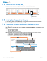
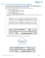
4. Record the Dell Service Tag Locate and record the number from the black Dell Service Tag on the front of the base enclosure. Dell Service Tag 5. Install optional expansion enclosures For each additional expansion enclosure, repeat steps 2 and 3 to install the rails and expansion enclosure onto the rails. If you are not installing an expansion enclosure, continue to step 7. 6. Connect the expansion enclosure to the base enclosure Before you begin: Select a single color of cable labels for use on all the enclosures in the appliance. Apply cable labels at each end of the following cables: - Node to first expansion enclosure - Node to last expansion enclosure - Expansion enclosure to expansion enclosure Cable both embedded modules on the base enclosure to the link control card (LCC) on the new expansion enclosure: 1. Connect node A, SAS port B to LCC A, port A on the expansion enclosure ( 1 ). 2. Connect node B, SAS port B to LCC B, port A on the expansion enclosure ( 2 ). 3. Connect node B, SAS port A to LCC A, port B on the expansion enclosure ( 3 ). 4. Connect node A, SAS port A to LCC B, port B on the expansion enclosure ( 4 ). 4 2 Expansion enclosure 1 B A 3 1 Node B A Dell EMC PowerStore Quick Start Guide Page 4 of 8
-
 1
1 -
 2
2 -
 3
3 -
 4
4 -
 5
5 -
 6
6 -
 7
7 -
 8
8
 |
 |
