Dell PowerStore 7000T EMC PowerStore Quick Start Guide - Page 5
Connect the base enclosure to your switches
 |
View all Dell PowerStore 7000T manuals
Add to My Manuals
Save this manual to your list of manuals |
Page 5 highlights
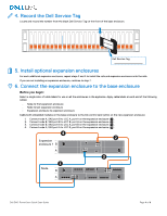
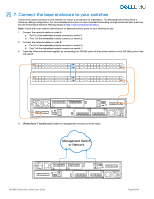
7. Connect the base enclosure to your switches Connect your base enclosure to two switches to ensure a strong layer of redundancy. The following instructions show a minimum cabling configuration. For more detailed instructions on recommended networking configurations and best practices, see the PowerStore Network Planning Guide at http://dell.com/powerstoredocs. Note: Check with your network administrator to determine which ports on your switches to use. 1. Connect the network cables on node A: a. Port 0 of the embedded module connects to switch 1. b. Port 1 of the embedded module connects to switch 2. 2. Connect the network cables on node B: a. Port 0 of the embedded module connects to switch 2. b. Port 1 of the embedded module connects to switch 1. 3. Cable the Ethernet switches together by connecting two 100GbE ports of the bottom switch to two 100 GbE ports of the top switch. 4. (PowerStore T models only) Cable the management interface on both nodes. Management Switch or Network Dell EMC PowerStore Quick Start Guide Page 5 of 8
-
 1
1 -
 2
2 -
 3
3 -
 4
4 -
 5
5 -
 6
6 -
 7
7 -
 8
8
 |
 |
