Dell PowerStore 9000X EMC PowerStore Network Planning Guide
Dell PowerStore 9000X Manual
 |
View all Dell PowerStore 9000X manuals
Add to My Manuals
Save this manual to your list of manuals |
Dell PowerStore 9000X manual content summary:
- Dell PowerStore 9000X | EMC PowerStore Network Planning Guide - Page 1
Dell EMC PowerStore Network Planning Guide Version 1.x September 2020 Rev. A02 - Dell PowerStore 9000X | EMC PowerStore Network Planning Guide - Page 2
use of your product. CAUTION: A CAUTION indicates either potential damage to hardware or loss of data and tells you how to avoid the problem. WARNING: A WARNING indicates a potential for property damage, personal injury, or death. © 2020 Dell Inc. or its subsidiaries. All rights reserved. Dell, EMC - Dell PowerStore 9000X | EMC PowerStore Network Planning Guide - Page 3
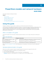
and network hardware overview 6 Using this guide...6 PowerStore deployment models...7 PowerStore appliance nodes...7 Top-of-Rack (ToR) switches...8 Dell EMC PowerSwitch S4148F-ON...9 Dell EMC PowerSwitch S4148T-ON...9 Dell PowerSwitch S5248F-ON...10 PowerStore logical topology...11 Top-of-Rack (ToR - Dell PowerStore 9000X | EMC PowerStore Network Planning Guide - Page 4
Network Setup Preparation Worksheet 40 Appendix C: PowerStore Initial Configuration Worksheets 42 PowerStore Initial Configuration Worksheet (blank 42 PowerStore T model: example of a completed Initial Configuration Worksheet 44 PowerStore X model: example of a completed Initial Configuration - Dell PowerStore 9000X | EMC PowerStore Network Planning Guide - Page 5
PowerStore Documentation page at https:// www.dell.com/powerstoredocs. ● Troubleshooting For information about products, software updates, licensing, and service, go to https://www.dell.com/support and locate the appropriate product support page. ● Technical support For technical support and service - Dell PowerStore 9000X | EMC PowerStore Network Planning Guide - Page 6
guide describes the requirements to deploy PowerStore with: ● A single cluster consisting of one appliance with a single base enclosure ● Two Top-of-Rack (ToR) switches ● One out-of-band (OOB) management switch for PowerStore T model deployments NOTE: PowerStore X model deployment is not supported - Dell PowerStore 9000X | EMC PowerStore Network Planning Guide - Page 7
customer applications within the hardware. NOTE: File (network attached storage (NAS)) services are not supported on this model. Part 2: Deploying PowerStore X model Switches and Networks PowerStore appliance nodes PowerStore appliances are deployed with a minimum of one base enclosure. Each base - Dell PowerStore 9000X | EMC PowerStore Network Planning Guide - Page 8
at the top-ofthe PowerStore hardware rack. Supported switches See the PowerStore Support Matrix for the list of supported switches. The Support Matrix is available from the Dell support site at:https://www.dell.com/support. Deploying with PowerSwitch Series PowerStore can be purchased with - Dell PowerStore 9000X | EMC PowerStore Network Planning Guide - Page 9
done through the serial console port. Serial Console Port Management Port Figure 4. S4000 series PSU-side Dell EMC PowerSwitch S4148T-ON Connectivity to PowerStore nodes is through the ports on the I/O panel. Figure 5. S4148T-ON switch I/O-side ● 48x10 GBASE-T ● 4x10/25/40/50/100GbE Connectivity to - Dell PowerStore 9000X | EMC PowerStore Network Planning Guide - Page 10
Dell PowerSwitch S5248F-ON You can configure PowerStore with dual Dell PowerSwitch S5248F-ON switch models. Figure 7. S5248F-ON I/O-side ● 48x25GbE ● 4x10/25 the serial console port. Management Port Figure 8. S5248 PSU-side Serial Console Port 10 PowerStore models and network hardware overview - Dell PowerStore 9000X | EMC PowerStore Network Planning Guide - Page 11
diagrams demonstrate the logical network topology for a PowerStore T model deployment, and a PowerStore X model deployment. PowerStore T model logical topology Management Production ToR 1 ToR 2 Embedded module Embedded module PowerStore T base enclosure Management Subnets Remote Discovery - Dell PowerStore 9000X | EMC PowerStore Network Planning Guide - Page 12
and network paths Top-of-Rack (ToR) switch connectivity options and requirements PowerStore requires connectivity to a pair of Top-of-Rack (ToR) switches. This to at least one out-of-band management switch. See PowerStore T model appliance out-of-band management switch requirements for details - Dell PowerStore 9000X | EMC PowerStore Network Planning Guide - Page 13
MC-LAG) interconnect It is highly recommended that you deploy PowerStore with an MC-LAG interconnect between the two ToR switches. the high speed ports are located on your switch. ● Use two cables that support connectivity between the high speed ports. For example 100Gbps Direct Attached Cables (DAC) - Dell PowerStore 9000X | EMC PowerStore Network Planning Guide - Page 14
Using a reliable L2 (Ethernet level) connection through the uplinks to connect the ToR switches is an acceptable alternative to MC-LAG for PowerStore deployments. With a reliable L2 connection you can port-channel the uplinks on each physical switch, which requires creating two portchannels instead - Dell PowerStore 9000X | EMC PowerStore Network Planning Guide - Page 15
switches ● Port 0 on Node A, and Port 0 on Node B must connect to opposite switches ● Port 1 on Node A, and Port 1 on Node B must connect to opposite switches PowerStore models and network hardware overview 15 - Dell PowerStore 9000X | EMC PowerStore Network Planning Guide - Page 16
I PowerStore T model: Network Planning Topics: • PowerStore T model out-of-band management switch • PowerStore T model: Network configuration requirements • Prepare to configure the networks 16 PowerStore T model: Network Planning - Dell PowerStore 9000X | EMC PowerStore Network Planning Guide - Page 17
management switch can be configured with or without a management VLAN. ● The OOB management switch ports must support untagged native VLAN traffic for remote discovery. See PowerStore T model appliance networks. in the following chapter for a description of the networks which run over the management - Dell PowerStore 9000X | EMC PowerStore Network Planning Guide - Page 18
Layer 3 - Management Uplinks Management Uplink A Management Uplink B Port Channel Layer 3 - OOB Management Switch Figure 15. Out-of-band management switch uplink connections 18 PowerStore T model out-of-band management switch - Dell PowerStore 9000X | EMC PowerStore Network Planning Guide - Page 19
T model with multiple and unique VLANs to separate the traffic. However, if only one VLAN is available, you have the option to deploy PowerStore T model with a single VLAN and multiple unique subnets as demonstrated below. Management Production ToR 1 ToR 2 Embedded module Embedded module - Dell PowerStore 9000X | EMC PowerStore Network Planning Guide - Page 20
ports Dedicated 1 GbE Management Management network traffic which provides access to: ● Infrastructure services such as DNS, NTP, and SMTP. ● PowerStore REST API, PowerStore Manager, and PowerStore CLI ● SupportAssist ● VASA provider Out-of-band management Dedicated 1 GbE Management Storage - Dell PowerStore 9000X | EMC PowerStore Network Planning Guide - Page 21
Initial Configuration Wizard. ● Storage network can be created for iSCSI traffic the first time you create a cluster through the PowerStore Initial Configuration Wizard (ICW). However, you have the option of skipping this step in the ICW if you're using Fibre Channel only. If you - Dell PowerStore 9000X | EMC PowerStore Network Planning Guide - Page 22
(based on the 802.1q standard), and the network takes on the native VLAN. The traffic on that network is passed as untagged in PowerStore, and the Native VLAN is applied to the untagged traffic through the switch. IP address requirements for initial configuration You will need IP addresses to - Dell PowerStore 9000X | EMC PowerStore Network Planning Guide - Page 23
in the future. IP address requirements for NAS servers After you have deployed PowerStore T model, you can add NAS servers for file storage through the PowerStore Manager, REST API, or CLI. See the PowerStore File Capabilities White Paper for specific details for configuring your NAS servers - Dell PowerStore 9000X | EMC PowerStore Network Planning Guide - Page 24
networks. A completed Network Setup Preparation Worksheet has been provided for you to use with the steps provided in the PowerStore Network Configuration Guide for Dell PowerSwitch Series. A completed Initial Configuration Worksheets has also been provided for your reference. Deployment with third - Dell PowerStore 9000X | EMC PowerStore Network Planning Guide - Page 25
II PowerStore X model: Network Planning Topics: • PowerStore X model: Network configuration requirements • Prepare to configure the networks PowerStore X model: Network Planning 25 - Dell PowerStore 9000X | EMC PowerStore Network Planning Guide - Page 26
if only one VLAN is available, you have the option to deploy PowerStore X model with a single VLAN and multiple unique subnets as demonstrated below. Figure 17. PowerStore X model network traffic Ensure that the PowerStore X model interfaces are able to communicate to each other through the VLANs - Dell PowerStore 9000X | EMC PowerStore Network Planning Guide - Page 27
) Network Types of traffic Management network traffic which provides access to: ● Infrastructure services such as DNS, NTP, and SMTP. ● PowerStore REST API, PowerStore Manager, and PowerStore CLI ● SupportAssist ● vCenter Storage network (block) traffic and external data mobility traffic - Dell PowerStore 9000X | EMC PowerStore Network Planning Guide - Page 28
(based on the 802.1q standard), and the network takes on the native VLAN. The traffic on that network is passed as untagged in PowerStore, and the Native VLAN is applied to the untagged traffic through the switch. IP addresses for network configuration You will need IP addresses to configure - Dell PowerStore 9000X | EMC PowerStore Network Planning Guide - Page 29
. You can use different IP versions for different networks for example, you can use IPv4 for the management network, and IPv6 for the storage network. PowerStore X model: Network configuration requirements 29 - Dell PowerStore 9000X | EMC PowerStore Network Planning Guide - Page 30
networks. A completed Network Setup Preparation Worksheet has been provided for you to use with the steps provided in the PowerStore Network Configuration Guide for Dell PowerSwitch Series. A completed Initial Configuration Worksheets has also been provided for your reference. Deployment with third - Dell PowerStore 9000X | EMC PowerStore Network Planning Guide - Page 31
/central/solutions. ● Ensure that your workstation's Ethernet adapter is configured as follows: ○ Connected directly to the PowerStore service port on node A. ○ Configured with a static IP address on the service LAN network (128.221.1.0/24) with no gateway address defined (128.221.1.249; 255.255.255 - Dell PowerStore 9000X | EMC PowerStore Network Planning Guide - Page 32
, ensure that you exit and restart the Discovery Utility after temporarily disabling the firewall or antivirus services. 1. From your workstation or virtual machine, launch the PowerStore Discovery Utility. 2. Select the unconfigured base enclosure for which you want to create a cluster. 3. Log on - Dell PowerStore 9000X | EMC PowerStore Network Planning Guide - Page 33
the reserved resources. 2. Print out the Initial Configuration Worksheet to record the additional network resources you will need to create networks in PowerStore T model the first time you create a cluster. 3. Determine which of the Top-of-Rack (ToR) switch ports will be connected to the - Dell PowerStore 9000X | EMC PowerStore Network Planning Guide - Page 34
of-band management switch Management IP address for switch 1 Management IP address for switch 2 Default gateway NTP server 10. Dell EMC supports deploying PowerStore T model with two Top-of-Rack (ToR) switches with a layer 2 interconnect link. Choose which type of layer 2 interconnect you will - Dell PowerStore 9000X | EMC PowerStore Network Planning Guide - Page 35
The examples of the network resources listed below are used in the deployment steps described in the PowerStore Network Configuration Guide for Dell PowerSwitch Series. Table 13. PowerStore T model Network Setup Preparation Worksheet (example) Step Step details 1. Print this table to record the - Dell PowerStore 9000X | EMC PowerStore Network Planning Guide - Page 36
/24 Management IP address for switch 2 100.0.100.11/24 Default gateway 100.0.100.1 NTP server 100.0.100.200 10. Dell EMC supports deploying PowerStore T model with two Top-of-Rack (ToR) switches with a layer 2 interconnect link. Choose which type of layer 2 interconnect you will use: Highly - Dell PowerStore 9000X | EMC PowerStore Network Planning Guide - Page 37
if you will use a direct connection or a remote connection to discover your PowerStore. Once you have successfully discovered your PowerStore, you will be guided through the Initial Configuration Wizard to create your first PowerStore cluster. PowerStore Network Setup Preparation Worksheets 37 - Dell PowerStore 9000X | EMC PowerStore Network Planning Guide - Page 38
configure the switch below: Management IP address for switch 1 Management IP address for switch 2 Default gateway NTP server 8. Dell EMC supports deploying PowerStore X model with two Top-of-Rack (ToR) switches with a layer 2 interconnect link. Choose which type of layer 2 interconnect you - Dell PowerStore 9000X | EMC PowerStore Network Planning Guide - Page 39
if you will use a direct connection or a remote connection to discover your PowerStore. Once you have successfully discovered your PowerStore, you will be guided through the Initial Configuration Wizard to create your first PowerStore cluster. PowerStore Network Setup Preparation Worksheets 39 - Dell PowerStore 9000X | EMC PowerStore Network Planning Guide - Page 40
steps described in the PowerStore Network Configuration Guide for Dell PowerSwitch Series. Table 15. PowerStore X model Network Setup /24 Default gateway 100.0.100.1 NTP server 100.0.100.200 8. Dell EMC supports deploying PowerStore X model with two Top-of-Rack (ToR) switches with a layer 2 - Dell PowerStore 9000X | EMC PowerStore Network Planning Guide - Page 41
if you will use a direct connection or a remote connection to discover your PowerStore. Once you have successfully discovered your PowerStore, you will be guided through the Initial Configuration Wizard to create your first PowerStore cluster. PowerStore Network Setup Preparation Worksheets 41 - Dell PowerStore 9000X | EMC PowerStore Network Planning Guide - Page 42
available with the product and feature documentation on the PowerStore Documentation page at https://www.dell.com/powerstoredocs. Table each type of network. Cluster IP Address Management Network Connects the cluster to services such as DNS and NTP. The IP addresses in the management network are - Dell PowerStore 9000X | EMC PowerStore Network Planning Guide - Page 43
used for a dedicated network that transfer virtual machines between appliances. 2 IPs for each PowerStore X model Appliance VLAN (Optional, Defaults to 0) Netmask/Prefix Length Gateway IP Addresses Infrastructure Services Record IP addresses for your DNS and NTP servers. It is recommended that - Dell PowerStore 9000X | EMC PowerStore Network Planning Guide - Page 44
system monitoring capability. It sends notifications to Dell EMC, enables remote support, and sends data to CloudIQ. Once your cluster is created successfully steps described in the PowerStore Network Configuration Guide for Dell PowerSwitch Series. Table 17. PowerStore T model: completed example - Dell PowerStore 9000X | EMC PowerStore Network Planning Guide - Page 45
subnet for each type of network. Management Network Connects the cluster to services such as DNS and NTP. The IP addresses in the management network 10 Netmask/Prefix Length Gateway 4 IPs for each PowerStore T model Appliance 6 IPs for each PowerStore X model Appliance IP Addresses 0 255.255.255 - Dell PowerStore 9000X | EMC PowerStore Network Planning Guide - Page 46
each PowerStore X model Appliance VLAN (Optional, Defaults to 0) Netmask/Prefix Length Gateway IP Addresses N/A N/A N/A N/A Infrastructure Services monitoring capability. It sends notifications to Dell EMC, enables remote support, and sends data to CloudIQ. Once your cluster is created - Dell PowerStore 9000X | EMC PowerStore Network Planning Guide - Page 47
for Direct Connect without remote access or Gateway Connect) PowerStore X model: example of a completed Initial Configuration Worksheet network. Cluster IP Address 192.168.1.10 Management Network Connects the cluster to services such as DNS and NTP. The IP addresses in the management network - Dell PowerStore 9000X | EMC PowerStore Network Planning Guide - Page 48
network that transfer virtual machines between appliances. 2 IPs for each PowerStore X model Appliance VLAN (Optional, Defaults to 0) Netmask/Prefix Length 400 255.255.255.0/24 192.168.4.1 192.168.4.10-11 Infrastructure Services Record IP addresses for your DNS and NTP servers. It is - Dell PowerStore 9000X | EMC PowerStore Network Planning Guide - Page 49
N/A N/A User Credentials / N/A N/A Community String PowerStore X model Only Hypervisor Record your existing vCenter administrator system monitoring capability. It sends notifications to Dell EMC, enables remote support, and sends data to CloudIQ. Once your cluster is created successfully,
-
 1
1 -
 2
2 -
 3
3 -
 4
4 -
 5
5 -
 6
6 -
 7
7 -
8
-
9
-
10
-
11
-
12
-
13
-
14
-
15
-
16
-
17
-
18
-
19
-
20
-
21
-
22
-
23
-
24
-
25
-
26
-
27
-
28
-
29
-
30
-
31
-
32
-
33
-
34
-
35
-
36
-
37
-
38
-
39
-
40
-
41
-
42
-
43
-
44
-
45
-
46
-
47
-
48
-
49
 |
 |

Dell EMC PowerStore
Network Planning Guide
Version 1.x
September 2020
Rev. A02