Dell PowerStore 9000X EMC PowerStore Network Planning Guide - Page 7
PowerStore deployment models, PowerStore appliance nodes, Supporting documentation
 |
View all Dell PowerStore 9000X manuals
Add to My Manuals
Save this manual to your list of manuals |
Page 7 highlights
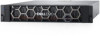
Supporting documentation In addition to reading through this document, you should also read through the following guides, prior to configuring your switches and networks: ● PowerStore Planning Guide ● PowerStore Hardware Information Guide PowerStore deployment models The different PowerStore models support different types of storage. Table 2. PowerStore deployment models Deployment Model numbers Supported configuration PowerStore T model appliance ● 1000T ● 3000T ● 5000T ● 7000T ● 9000T Supports block (Storage Area Network (SAN)), file (Network Attached Storage (NAS)), and Virtual Volume (vVol) workloads with the software stack deployed directly on the bare metal of the system. NOTE: Hypervisor deployments are not supported on this model. Refer to Part 1: Deploying PowerStore T model Switches and Networks PowerStore X model appliance ● 1000X ● 3000X ● 5000X ● 7000X ● 9000X Supports block (SAN-only), and vVol workloads with a hypervisor installed on the system. The system software is deployed on the hypervisor, which enables deployment of virtual machines (VMs) and customer applications within the hardware. NOTE: File (network attached storage (NAS)) services are not supported on this model. Part 2: Deploying PowerStore X model Switches and Networks PowerStore appliance nodes PowerStore appliances are deployed with a minimum of one base enclosure. Each base enclosure consists of two nodes. A base enclosure consists of two nodes. Node A is the bottom node and Node B is the top node (flipped upside down in enclosure). The port layouts on both nodes are the same. 3 4 4 2 1 2 1 3 4 4 1 4-port card 2 Management ports 3 Service ports 4 I/O Module Figure 1. PowerStore base enclosure nodes and ports PowerStore models and network hardware overview 7
-
 1
1 -
 2
2 -
 3
3 -
 4
4 -
 5
5 -
 6
6 -
 7
7 -
 8
8 -
 9
9 -
 10
10 -
 11
11 -
 12
12 -
13
-
14
-
15
-
16
-
17
-
18
-
19
-
20
-
21
-
22
-
23
-
24
-
25
-
26
-
27
-
28
-
29
-
30
-
31
-
32
-
33
-
34
-
35
-
36
-
37
-
38
-
39
-
40
-
41
-
42
-
43
-
44
-
45
-
46
-
47
-
48
-
49
 |
 |
