Dell Precision 530 Memory Riser Board Replacement - Page 10
System Memory Installation Guidelines, Riser Board Installation
 |
View all Dell Precision 530 manuals
Add to My Manuals
Save this manual to your list of manuals |
Page 10 highlights
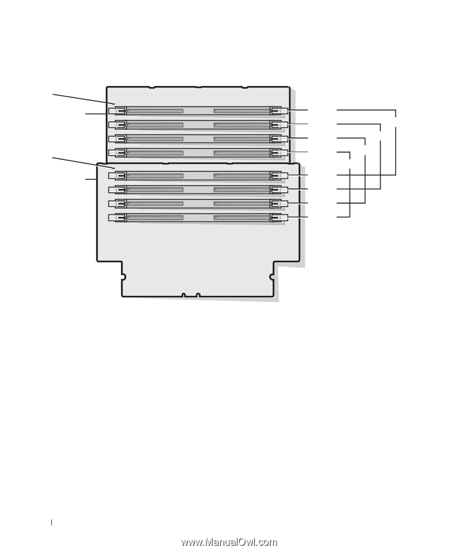
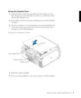
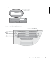
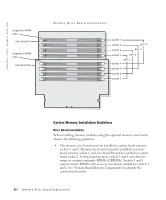
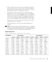
w w w.d el l.co m | su p po rt. d ell. com suspend-to-RAM light riser board A suspend-to-RAM light riser board B Memory Riser Board Components socket 4 socket 3 pair 4 socket 2 pair 3 socket 1 pair 2 pair 1 socket 4 socket 3 socket 2 socket 1 System Memory Installation Guidelines Riser Board Installation When installing memory modules using the optional memory riser boards, observe the following guidelines: • The memory riser boards must be installed in system board memory sockets 1 and 2. Memory riser board A must be installed in system board memory socket 1, and riser board B must be installed in system board socket 2. System board memory sockets 3 and 4 can either be empty or contain continuity RIMMs (CRIMMs). Sockets 3 and 4 cannot contain RIMMs with memory riser boards installed in sockets 1 and 2. See "System Board Memory Components" to identify the system board sockets. 10 M em o r y Ri s e r B o a rd Rep l a c em e n t
-
 1
1 -
2
-
3
-
4
-
 5
5 -
 6
6 -
 7
7 -
 8
8 -
 9
9 -
 10
10 -
 11
11 -
 12
12 -
 13
13 -
 14
14 -
 15
15 -
16
-
17
-
18
-
19
-
20
-
21
-
22
-
23
-
24
-
25
-
26
-
27
-
28
-
29
-
30
-
31
-
32
-
33
-
34
-
35
-
36
-
37
-
38
-
39
-
40
-
41
-
42
-
43
-
44
-
45
-
46
-
47
-
48
-
49
-
50
-
51
-
52
-
53
-
54
-
55
-
56
-
57
-
58
-
59
-
60
-
61
-
62
-
63
-
64
-
65
-
66
-
67
-
68
-
69
-
70
-
71
-
72
-
73
-
74
-
75
-
76
-
77
-
78
-
79
-
80
-
81
-
82
-
83
-
84
-
85
-
86
-
87
 |
 |