Dell Precision 530 Memory Riser Board Replacement - Page 19
Installing Memory Riser Boards, Memory Components.
 |
View all Dell Precision 530 manuals
Add to My Manuals
Save this manual to your list of manuals |
Page 19 highlights
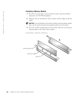
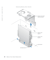
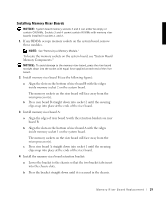
Installing Memory Riser Boards NOTICE: System board memory sockets 3 and 4 can either be empty or contain CRIMMs. Sockets 3 and 4 cannot contain RIMMs with memory riser boards installed in sockets 1 and 2. 1 If any RIMMs occupy memory sockets on the system board, remove those modules. NOTE: See "Removing a Memory Module." To locate the memory sockets on the system board, see "System Board Memory Components." NOTICE: To avoid damage to the memory riser board, press the riser board straight down into the socket with equal force applied at each end of the riser board. 2 Install memory riser board B (see the following figure): a Align the slots on the bottom of riser board B with the ridges inside memory socket 2 on the system board. The memory sockets on the riser board will face away from the microprocessor(s). b Press riser board B straight down into socket 2 until the securing clips snap into place at the ends of the riser board. 3 Install memory riser board A: a Align the edges of riser board A with the retention brackets on riser board B. b Align the slots on the bottom of riser board A with the ridges inside memory socket 1 on the system board. The memory sockets on the riser board will face away from the microprocessor(s). c Press riser board A straight down into socket 1 until the securing clips snap into place at the ends of the riser board. 4 Install the memory riser board retention bracket: a Lower the bracket to the chassis so that the two bracket tabs insert into the chassis slots. b Press the bracket straight down until it is secured in the chassis. M e mo r y R i s er B o a rd Re p la c e m en t 19
-
 1
1 -
2
-
3
-
4
-
5
-
6
-
7
-
8
-
9
-
10
-
11
-
12
-
13
-
 14
14 -
 15
15 -
 16
16 -
 17
17 -
 18
18 -
 19
19 -
 20
20 -
 21
21 -
 22
22 -
 23
23 -
 24
24 -
25
-
26
-
27
-
28
-
29
-
30
-
31
-
32
-
33
-
34
-
35
-
36
-
37
-
38
-
39
-
40
-
41
-
42
-
43
-
44
-
45
-
46
-
47
-
48
-
49
-
50
-
51
-
52
-
53
-
54
-
55
-
56
-
57
-
58
-
59
-
60
-
61
-
62
-
63
-
64
-
65
-
66
-
67
-
68
-
69
-
70
-
71
-
72
-
73
-
74
-
75
-
76
-
77
-
78
-
79
-
80
-
81
-
82
-
83
-
84
-
85
-
86
-
87
 |
 |