Dell Precision 530 Memory Riser Board Replacement - Page 17
Removing Memory Riser Boards, simultaneously until riser board A pops out slightly from - processor
 |
View all Dell Precision 530 manuals
Add to My Manuals
Save this manual to your list of manuals |
Page 17 highlights
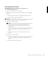
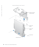
Removing Memory Riser Boards CAUTION: B ef or e you p e r fo rm t hi s pr oc e d ur e , s e e "Precautionary Measures." 1 Remove the microprocessor airflow shroud. 2 Remove the memory riser board retention bracket (see the following figure). a Lift the retention bracket up to disengage it from the chassis. b Lift the bracket away from the chassis. NOTICE: To avoid damage to the memory riser board, press the securing clips with equal force applied at each end of the memory socket. 3 Remove memory riser board A: NOTE: To access the securing clips on the system board memory sockets, it may be necessary to remove the fan for microprocessor 0. For instructions on removing and installing the processor fan, see the Service Manual. a Press the securing clips of system board memory socket 1 outward simultaneously until riser board A pops out slightly from the socket. b Lift riser board A away from the retention brackets on riser board B. 4 Remove memory riser board B: a Press the securing clips of system board memory socket B outward simultaneously until riser board B pops out slightly from the socket. b Lift riser board B away from socket 2. M e mo r y R i s er B o a rd Re p la c e m en t 17
-
 1
1 -
2
-
3
-
4
-
5
-
6
-
7
-
8
-
9
-
10
-
11
-
 12
12 -
 13
13 -
 14
14 -
 15
15 -
 16
16 -
 17
17 -
 18
18 -
 19
19 -
 20
20 -
 21
21 -
 22
22 -
23
-
24
-
25
-
26
-
27
-
28
-
29
-
30
-
31
-
32
-
33
-
34
-
35
-
36
-
37
-
38
-
39
-
40
-
41
-
42
-
43
-
44
-
45
-
46
-
47
-
48
-
49
-
50
-
51
-
52
-
53
-
54
-
55
-
56
-
57
-
58
-
59
-
60
-
61
-
62
-
63
-
64
-
65
-
66
-
67
-
68
-
69
-
70
-
71
-
72
-
73
-
74
-
75
-
76
-
77
-
78
-
79
-
80
-
81
-
82
-
83
-
84
-
85
-
86
-
87
 |
 |
