Dell Precision 530 Memory Riser Board Replacement - Page 15
Removing a Memory Module, total is correct, exit system setup. - manual
 |
View all Dell Precision 530 manuals
Add to My Manuals
Save this manual to your list of manuals |
Page 15 highlights
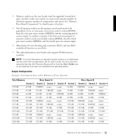
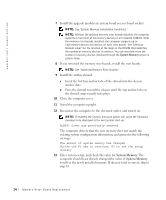
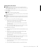
14 If the memory total is incorrect, repeat step 1 through step 3. Check the installed modules and riser boards to ensure that they are seated properly in their sockets. Then repeat step 10 through step 13. 15 When the System Memory total is correct, exit system setup. NOTE: For more information about system setup see your User's Guide. 16 Turn off the computer, and attach the devices to the computer and electrical outlets. Removing a Memory Module CAUTION: B ef or e you p e r fo rm t hi s pr oc e d ur e , s e e "Precautionary Measures." NOTICE: To avoid damage to the memory module, press the securing clips with equal force applied at each end of the memory socket. 1 Press the securing clips at each end of the memory socket outward simultaneously until the module pops out slightly from the socket (see the following figure). NOTE: To access the securing clips on the system board memory sockets, it may be necessary to remove the fan for microprocessor 0. For instructions on removing and installing the processor fan, see the Service Manual. 2 Lift the module away from the socket. Removing a Memory Module securing clips (2) memory socket M e mo r y R i s er B o a rd Re p la c e m en t 15
-
 1
1 -
2
-
3
-
4
-
5
-
6
-
7
-
8
-
9
-
 10
10 -
 11
11 -
 12
12 -
 13
13 -
 14
14 -
 15
15 -
 16
16 -
 17
17 -
 18
18 -
 19
19 -
 20
20 -
21
-
22
-
23
-
24
-
25
-
26
-
27
-
28
-
29
-
30
-
31
-
32
-
33
-
34
-
35
-
36
-
37
-
38
-
39
-
40
-
41
-
42
-
43
-
44
-
45
-
46
-
47
-
48
-
49
-
50
-
51
-
52
-
53
-
54
-
55
-
56
-
57
-
58
-
59
-
60
-
61
-
62
-
63
-
64
-
65
-
66
-
67
-
68
-
69
-
70
-
71
-
72
-
73
-
74
-
75
-
76
-
77
-
78
-
79
-
80
-
81
-
82
-
83
-
84
-
85
-
86
-
87
 |
 |