Dell XPS 400 9150 XPS 400/Dimension 9150 Service Manual
Dell XPS 400 9150 Manual
 |
View all Dell XPS 400 9150 manuals
Add to My Manuals
Save this manual to your list of manuals |
Dell XPS 400 9150 manual content summary:
- Dell XPS 400 9150 | XPS 400/Dimension 9150 Service Manual - Page 1
Dell XPS 400 Service Manual Dell™ XPS™ 400 Service Manual About Your Computer Before You Begin Removing the Computer Cover Technical Overview Specifications Advanced Troubleshooting System Setup Removing and Installing Parts Replacing the Computer Cover Notes, Notices, and Cautions NOTE: A NOTE - Dell XPS 400 9150 | XPS 400/Dimension 9150 Service Manual - Page 2
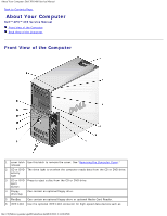
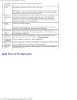
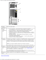
Dell XPS 400 Service Manual Back to Contents Page About Your Computer Dell™ XPS™ 400 Service Manual Front View of the Computer Back View of the Computer Front View of the Computer 1 cover latch Use this latch to remove the cover. See "Removing the Computer Cover." release 2 CD or DVD The drive - Dell XPS 400 9150 | XPS 400/Dimension 9150 Service Manual - Page 3
About Your Computer: Dell XPS 400 Service Manual connector (optional) 7 vents digital video cameras and external storage devices hard drive. The light might also be on when a device such as a CD player is operating. 11 diagnostic Use the lights to help you troubleshoot a computer problem based on - Dell XPS 400 9150 | XPS 400/Dimension 9150 Service Manual - Page 4
About Your Computer: Dell XPS 400 Service Manual 1 power Insert the power cable. connector 2 sound card connectors (5) Line-in connector - Use the blue line-in connector to attach a record/playback device such as a cassette player, CD player, or VCR. Line-out - Dell XPS 400 9150 | XPS 400/Dimension 9150 Service Manual - Page 5
About Your Computer: Dell XPS 400 Service Manual file:///T|/htdocs/systems/xps400/sm/about.htm[8/3/2012 3:11:06 PM] - Dell XPS 400 9150 | XPS 400/Dimension 9150 Service Manual - Page 6
Begin: Dell XPS 400 Service Manual Back to Contents Page Before You Begin Dell™ XPS™ 400 Service Manual Getting Started Recommended Tools Turning Off Your Computer Before Working Inside Your Computer Getting Started This chapter provides procedures for removing and installing the components - Dell XPS 400 9150 | XPS 400/Dimension 9150 Service Manual - Page 7
: Dell XPS 400 Service Manual Before Working Inside Your Computer Use the following safety guidelines to help protect your computer from potential damage and to help ensure your own personal safety. CAUTION: Before you begin any of the procedures in this section, follow the safety instructions in - Dell XPS 400 9150 | XPS 400/Dimension 9150 Service Manual - Page 8
Removing the Computer Cover: Dell XPS 400 Service Manual Back to Contents Page Removing the Computer Cover Dell™ XPS™ 400 Service Manual CAUTION: Before you begin any of the procedures in this section, follow the safety instructions in the Product Information Guide. CAUTION: To guard against - Dell XPS 400 9150 | XPS 400/Dimension 9150 Service Manual - Page 9
Removing the Computer Cover: Dell XPS 400 Service Manual 6. Grip the sides of the computer cover and pivot the cover up. 7. Lift the cover away and set it aside in a secure location. Back to Contents Page file:///T|/htdocs/systems/xps400/sm/cvrop.htm[8/3/2012 3:11:08 PM] - Dell XPS 400 9150 | XPS 400/Dimension 9150 Service Manual - Page 10
Overview Dell™ XPS™ 400 Service Manual Inside View of Your Computer System Board Components Power Supply DC Connector Pin Assignments Inside View of Your Computer CAUTION: Before you begin any of the procedures in this section, follow the safety instructions in the Product Information Guide - Dell XPS 400 9150 | XPS 400/Dimension 9150 Service Manual - Page 11
Technical Overview: Dell XPS 400 Service Manual Power Supply DC Connector Pin Assignments file:///T|/htdocs/systems/xps400/sm/techov.htm[8/3/2012 3:11:13 PM] - Dell XPS 400 9150 | XPS 400/Dimension 9150 Service Manual - Page 12
Technical Overview: Dell XPS 400 Service Manual DC Power Connector P1 Pin Number Signal Name Color Wire Gauge 1 +3.3 VDC Orange 18-AWG 2 +3.3 VDC Orange 18-AWG 3 COM Black 18-AWG 4 +5 VDC Red - Dell XPS 400 9150 | XPS 400/Dimension 9150 Service Manual - Page 13
Technical Overview: Dell XPS 400 Service Manual 10 +12 VB DC White 18-AWG 11 +12VB DC White 18-AWG 12 +3.3 VDC Orange 18-AWG 13 +3.3 VDC Orange 18-AWG 14 -12 - Dell XPS 400 9150 | XPS 400/Dimension 9150 Service Manual - Page 14
Technical Overview: Dell XPS 400 Service Manual 4 COM Black 5 +12 VB DC White DC Power Connector P4 Pin Number Signal Name 18-AWG Wire 1 N/C N/C 2 COM Black 3 COM Black 4 +3.3 VDC Orange 5 +5 VDC Red 6 + - Dell XPS 400 9150 | XPS 400/Dimension 9150 Service Manual - Page 15
Technical Overview: Dell XPS 400 Service Manual 2 COM Black 3 COM Black 4 +5V DC Red NOTE: The P10 connector is intended for use with PCI Express graphics cards that have power requirements exceeding 75 watts. DC Power Connector P11 Pin Number Signal Name 18-AWG Wire 1 +12 VB DC White - Dell XPS 400 9150 | XPS 400/Dimension 9150 Service Manual - Page 16
: Dell Dimension 9150 Service Manual Back to Contents Page Specifications Dell™ XPS™ 400 Service Manual Processor Processor type Cache Intel® Pentium® 4 Socket-T with HyperThreading or Dual-Core support 2 MB Memory Type Memory connectors Memory capacities Minimum memory Maximum memory BIOS - Dell XPS 400 9150 | XPS 400/Dimension 9150 Service Manual - Page 17
Specifications: Dell Dimension 9150 Service Manual PCI drive bays serial ATA drives (2), floppy drive, USB memory devices, CD drive, CD-RW drive, DVD drive, DVD-RW drive, Media Card Reader, and DVD/CD-RW combo drive two 3.5-inch hard-drive bays Connectors External connectors: IEEE 1394 Video - Dell XPS 400 9150 | XPS 400/Dimension 9150 Service Manual - Page 18
Specifications: Dell Dimension 9150 Service Manual System board connectors: Primary IDE drive Serial ATA FlexBay Drive Fan PCI PCI Express the system cannot boot and there is a solid amber light, this indicates a problem with the system board (see "Power Lights"). Hard-drive access light green - Dell XPS 400 9150 | XPS 400/Dimension 9150 Service Manual - Page 19
Specifications: Dell Dimension 9150 Service Manual in the Product Information Guide for important voltage setting information.) Backup battery 135 V and 180 to 265 V at 50/60 Hz 50 to 10,000 ft) -15.2 to 10,668 m (-50 to 35,000 ft) file:///T|/htdocs/systems/xps400/sm/specs.htm[8/3/2012 3:11:15 PM] - Dell XPS 400 9150 | XPS 400/Dimension 9150 Service Manual - Page 20
: Dell XPS 400 Service Manual Back to Contents Page Advanced Troubleshooting Dell™ XPS™ 400 Service Manual Power Lights Diagnostic Lights Beep Codes Power Lights CAUTION: Before you begin any of the procedures in this section, follow the safety instructions in the Product Information Guide - Dell XPS 400 9150 | XPS 400/Dimension 9150 Service Manual - Page 21
Advanced Troubleshooting: Dell XPS 400 Service Manual To help you troubleshoot a problem, your computer has four lights labeled "1," "2," "3," and "4" on the front panel (see "Front View of the Computer"). When the computer starts normally, the lights flash. - Dell XPS 400 9150 | XPS 400/Dimension 9150 Service Manual - Page 22
Advanced Troubleshooting: Dell XPS 400 Service Manual Another failure has occurred. Ensure that the cables are properly connected to the system board from the hard drive, CD drive, and DVD drive (see "System Board Components"). If there is an error message on your screen identifying a problem with - Dell XPS 400 9150 | XPS 400/Dimension 9150 Service Manual - Page 23
Advanced Troubleshooting: Dell XPS 400 Service Manual 3-4-2 Screen retrace failure 3-4-3 Search for video ROM failure 4-2-1 No time tick 4-2-2 Shutdown failure 4-2-3 Gate A20 failure 4-2-4 Unexpected interrupt in protected mode 4-3-3 Timer-chip counter 2 failure 4-3-4 Time-of-day clock stopped 4-4-1 - Dell XPS 400 9150 | XPS 400/Dimension 9150 Service Manual - Page 24
Advanced Troubleshooting: Dell XPS 400 Service Manual Failure HDD Controller Failure communicate with the floppy drive or hard drive controller. INTR1 Error An interrupt channel on the INTR2 Error system board failed to POST. Invalid Boot Diskette The operating system cannot be located on drive - Dell XPS 400 9150 | XPS 400/Dimension 9150 Service Manual - Page 25
System Setup: Dell XPS 400 Service Manual Back to Contents Page System Setup Dell™ XPS™ 400 Service Manual Clearing Forgotten Passwords as the user password To read the current amount of memory or set the type of hard drive installed Before you use system setup, it is recommended that you - Dell XPS 400 9150 | XPS 400/Dimension 9150 Service Manual - Page 26
System Setup: Dell XPS 400 Service Manual Scroll up and down the list with the up- and down-arrow keys. As an option is highlighted, the Option Field displays more information about - Dell XPS 400 9150 | XPS 400/Dimension 9150 Service Manual - Page 27
System Setup: Dell XPS 400 Service Manual Determines the integrated SATA controller's operating mode: SATA Operation RAID Autodetect/ AHCI (the default setting) - RAID if the drives are signed, otherwise AHCI RAID Autodetect/ ATA - RAID if the drives are signed, otherwise ATA RAID On - SATA is - Dell XPS 400 9150 | XPS 400/Dimension 9150 Service Manual - Page 28
System Setup: Dell XPS 400 Service Manual AC Recovery Determines what happens when AC power is restored to the computer. On restarts the computer when power is restored after an outage. Last returns the computer to its last state before power was removed. Off is the default setting. Sets the - Dell XPS 400 9150 | XPS 400/Dimension 9150 Service Manual - Page 29
Setup: Dell XPS 400 Service Manual USB Flash Device - Insert the memory device into a USB port and restart the computer. When F12 = Boot Menu appears in the upper-right corner of the screen, press . The BIOS detects the device and adds the USB flash option to the boot menu. NOTE: To boot to - Dell XPS 400 9150 | XPS 400/Dimension 9150 Service Manual - Page 30
System Setup: Dell XPS 400 Service Manual 2. Locate the 3-pin password jumper (PSWD) on the system board, and remove the you begin any of the procedures in this section, follow the safety instructions in the Product Information Guide. 1. Follow the procedures in "Before You Begin." 2. Reset the - Dell XPS 400 9150 | XPS 400/Dimension 9150 Service Manual - Page 31
System Setup: Dell XPS 400 Service Manual a. Locate the 3-pin CMOS jumper (RTCRST) on the system board (see "Clearing Forgotten Passwords"). b. Remove the jumper plug from pins 1 and 2. c. Place the jumper plug - Dell XPS 400 9150 | XPS 400/Dimension 9150 Service Manual - Page 32
Removing and Installing Parts: Dell XPS 400 Service Manual Back to Contents Page Removing and Installing Parts Dell™ XPS™ 400 Service Manual Memory Cards Drive Panels Drives Hard Drive Floppy Drive Media Card Reader CD/DVD Drive Power Supply Processor I/O Panel Battery - Dell XPS 400 9150 | XPS 400/Dimension 9150 Service Manual - Page 33
Installing Parts: Dell XPS 400 Service Manual memory, the modules function at the slowest speed installed. Be sure to install a single memory module in the DIMM_1 connector, the connector closest to the processor, before you install modules in the other connectors. NOTE: Memory purchased from Dell - Dell XPS 400 9150 | XPS 400/Dimension 9150 Service Manual - Page 34
Removing and Installing Parts: Dell XPS 400 Service Manual 5. Align the notch on the bottom of the module with the crossbar in the connector. NOTICE: To avoid damage to the memory module, press the module straight down into the connector while you apply equal force to each end of the module. 6. - Dell XPS 400 9150 | XPS 400/Dimension 9150 Service Manual - Page 35
Removing and Installing Parts: Dell XPS 400 Service Manual If you insert the module memory is installed correctly, check the amount of memory (RAM) listed. Removing Memory CAUTION: Before you begin any of the procedures in this section, follow the safety instructions in the Product Information Guide - Dell XPS 400 9150 | XPS 400/Dimension 9150 Service Manual - Page 36
and Installing Parts: Dell XPS 400 Service Manual Your Dell™ computer provides the following slots for PCI and PCI Express cards: Three 33-MHz PCI card slots One PCI Express x1 card slot One PCI Express x16 card slot One PCI Express x4 card slot Removing and Installing PCI and PCI Express Cards NOTE - Dell XPS 400 9150 | XPS 400/Dimension 9150 Service Manual - Page 37
and Installing Parts: Dell XPS 400 Service Manual 4. Push the two release tabs on the card retention door from the inside to pivot the door open. Because the door is captive, it will remain in the open position. 5. If your computer includes a card retention mechanism: a. Grasp the end of the card - Dell XPS 400 9150 | XPS 400/Dimension 9150 Service Manual - Page 38
and Installing Parts: Dell XPS 400 Service Manual 7. If you are replacing or removing a card: a. If necessary, disconnect any cables connected to the card. b. Pull the securing tab (if present), grasp the card by its top corners, and ease it out of its connector. c. If you are not replacing the card - Dell XPS 400 9150 | XPS 400/Dimension 9150 Service Manual - Page 39
Removing and Installing Parts: Dell XPS 400 Service Manual 12. Ensure that: The tops of all cards and filler brackets are flush with the alignment bar. The notch in the top of the card or filler bracket fits around the alignment guide. 13. Close the card retention door by snapping it into place to - Dell XPS 400 9150 | XPS 400/Dimension 9150 Service Manual - Page 40
Removing and Installing Parts: Dell XPS 400 Service Manual 15. If a card retention mechanism is present on your computer, reseat it in its tabs, and rotate it down until it snaps into place. 16. If a "piano" bracket (for full-length PCI-E cards) is present on your computer, rotate it down into place - Dell XPS 400 9150 | XPS 400/Dimension 9150 Service Manual - Page 41
Removing and Installing Parts: Dell XPS 400 Service Manual If you removed an add-in network connector: 1. Enter system setup, select Integrated NIC Controller, and then change the setting to On. 2. Connect the network cable to the integrated connector on the back panel of the computer. Drive Panels - Dell XPS 400 9150 | XPS 400/Dimension 9150 Service Manual - Page 42
Removing and Installing Parts: Dell XPS 400 Service Manual Removing the Drive-Panel Insert NOTICE: Drive-panel inserts may contain screws on the inside. You can attach the screws to new drives that do not have any screws. NOTICE: To avoid breaking the drive-panel insert tab, do not pull the insert - Dell XPS 400 9150 | XPS 400/Dimension 9150 Service Manual - Page 43
and Installing Parts: Dell XPS 400 Service Manual Replacing the Drive Panel 1. Follow the procedures in "Before You Begin." 2. Align the drive panel tabs with the side-door hinges. 3. Rotate the drive panel toward the computer until the sliding plate lever clicks into place and the drive panel - Dell XPS 400 9150 | XPS 400/Dimension 9150 Service Manual - Page 44
Removing and Installing Parts: Dell XPS 400 Service Manual connector and the other will attach to the system board. Connect hard drives to data connectors labeled "SATA" and connect CD/DVD drives to connectors labeled "IDE". When you connect two IDE devices to a single IDE interface cable and - Dell XPS 400 9150 | XPS 400/Dimension 9150 Service Manual - Page 45
Removing and Installing Parts: Dell XPS 400 Service Manual CAUTION: To guard against electrical shock, always unplug your computer from the electrical outlet before opening the cover. NOTICE: To avoid damage to the drive, do not set it on a hard surface. Instead, set the drive on a surface, such as - Dell XPS 400 9150 | XPS 400/Dimension 9150 Service Manual - Page 46
Removing and Installing Parts: Dell XPS 400 Service Manual Installing a Hard Drive 1. Unpack the replacement hard drive, and prepare it for installation. 2. Check the documentation for the drive to verify that the drive is configured for your computer. 3. If your replacement hard drive does not have - Dell XPS 400 9150 | XPS 400/Dimension 9150 Service Manual - Page 47
Removing and Installing Parts: Dell XPS 400 Service Manual See the documentation that came with the hard drive for instructions about installing any software required for the operation of the hard drive. 10. If the drive you just installed is the primary drive, insert bootable media into drive A. 11 - Dell XPS 400 9150 | XPS 400/Dimension 9150 Service Manual - Page 48
Removing and Installing Parts: Dell XPS 400 Service Manual 6. Gently slide the drive into place until you feel a click or feel the drive securely installed. 7. Connect the power and SATA data cables to the drive. 8. Check all connectors to be certain that they are properly cabled and firmly seated. - Dell XPS 400 9150 | XPS 400/Dimension 9150 Service Manual - Page 49
Removing and Installing Parts: Dell XPS 400 Service Manual NOTE: If you are adding a floppy drive, see "Installing a Floppy Drive." Removing a Floppy Drive 1. Follow the procedures in "Before You Begin." 2. Remove the computer cover. 3. Disconnect the power and floppy drive cables from the back of - Dell XPS 400 9150 | XPS 400/Dimension 9150 Service Manual - Page 50
Removing and Installing Parts: Dell XPS 400 Service Manual Installing a Floppy Drive 1. If you are installing a new floppy drive, remove the shoulder screws from the inside of the drive-panel insert and attach the screws to the new drive. 2. Slide the floppy drive into the floppy drive bay until the - Dell XPS 400 9150 | XPS 400/Dimension 9150 Service Manual - Page 51
Removing and Installing Parts: Dell XPS 400 Service Manual 4. Remove the drive panel. 5. Disconnect the USB cable on the back of the Media Card Reader from the front panel USB connector on the system board (see "System Board Components") and remove the cable from the clip on the shroud. 6. - Dell XPS 400 9150 | XPS 400/Dimension 9150 Service Manual - Page 52
Removing and Installing Parts: Dell XPS 400 Service Manual 8. Replace the computer cover. Installing a Media Card Reader CAUTION: Before you begin any of the procedures in this section, follow the safety instructions in the Product Information Guide. NOTICE: To prevent static damage to components - Dell XPS 400 9150 | XPS 400/Dimension 9150 Service Manual - Page 53
Removing and Installing Parts: Dell XPS 400 Service Manual 8. Insert the Media Card Reader into the bay and slide the drive in to seat it in the computer. 9. Route the USB cable through the cable routing clip. 10. Replace the computer cover. CD/DVD Drive CAUTION: Before you begin any of the - Dell XPS 400 9150 | XPS 400/Dimension 9150 Service Manual - Page 54
and Installing Parts: Dell XPS 400 Service Manual 4. Slide the drive release mechanism to the right to release the shoulder screw and slide the drive out to remove it from the drive bay. Installing a CD/DVD Drive 1. If you are installing a new drive, unpack the drive and prepare it for installation - Dell XPS 400 9150 | XPS 400/Dimension 9150 Service Manual - Page 55
and Installing Parts: Dell XPS 400 Service Manual 3. Slide the drive into the drive bay until the drive clicks into position. 4. Connect the power cable to the drive and the CD/DVD cable to the drive and system board. 5. If you are installing a new CD/DVD drive rather than replacing a drive, remove - Dell XPS 400 9150 | XPS 400/Dimension 9150 Service Manual - Page 56
Removing and Installing Parts: Dell XPS 400 Service Manual Power Supply CAUTION: Before you begin any of the procedures in this section, follow the safety instructions in the Product Information Guide. Removing the Power Supply 1. Follow the procedures in "Before You Begin." 2. Disconnect the DC - Dell XPS 400 9150 | XPS 400/Dimension 9150 Service Manual - Page 57
Removing and Installing Parts: Dell XPS 400 Service Manual Replacing the Power Supply CAUTION: Before you begin any of the procedures in this section, follow the safety instructions in the Product Information Guide. 1. Slide the power supply into place. 2. Replace the four screws that secure the - Dell XPS 400 9150 | XPS 400/Dimension 9150 Service Manual - Page 58
Removing and Installing Parts: Dell XPS 400 Service Manual b. Set the retention mechanism aside in a secure installing a processor upgrade kit from Dell, discard the original heat sink. If you are not installing a processor upgrade kit from Dell, reuse the original heat sink when you install your new - Dell XPS 400 9150 | XPS 400/Dimension 9150 Service Manual - Page 59
Removing and Installing Parts: Dell XPS 400 Service Manual 6. Place your finger upon the hook end of the lever extended in the release position so that the socket is ready for the new processor. Installing the Processor NOTICE: Ground yourself by touching an unpainted metal surface on the back - Dell XPS 400 9150 | XPS 400/Dimension 9150 Service Manual - Page 60
Removing and Installing Parts: Dell XPS 400 Service Manual 3. Orient the front and rear alignment notches on the processor with the front and rear alignment notches on the socket. 4. Align the pin-1 corners of - Dell XPS 400 9150 | XPS 400/Dimension 9150 Service Manual - Page 61
Removing and Installing Parts: Dell XPS 400 Service Manual NOTICE: Ensure that the heat sink is correctly seated and begin any of the procedures in this section, follow the safety instructions in the Product Information Guide. CAUTION: To guard against electrical shock, always unplug your computer - Dell XPS 400 9150 | XPS 400/Dimension 9150 Service Manual - Page 62
and Installing Parts: Dell XPS 400 Service Manual 1 USB ports 2 diagnostic, hard-drive activity, and network lights 3 headphones connector 4 microphone connector Removing the I/O Panel 1. Follow the procedures in "Before You Begin." 2. Remove the computer cover. 3. If your computer includes a card - Dell XPS 400 9150 | XPS 400/Dimension 9150 Service Manual - Page 63
Removing and Installing Parts: Dell XPS 400 Service Manual b. Set the retention mechanism aside in a secure location. 4. Use a long Phillips screwdriver to loosen the two captive screws on each side of the heat-sink - Dell XPS 400 9150 | XPS 400/Dimension 9150 Service Manual - Page 64
Removing and Installing Parts: Dell XPS 400 Service Manual 1 heat sink and fan shroud assembly 2 captive screw housing (2) 3 drive panel 9. Lift the fan release lever, then slide the fan toward the back of the computer to release it from the bottom cover. 10. Remove - Dell XPS 400 9150 | XPS 400/Dimension 9150 Service Manual - Page 65
Removing and Installing Parts: Dell XPS 400 Service Manual 16. Remove the I/O panel from the computer. Replacing the I/O begin any of the procedures in this section, follow the safety instructions in the Product Information Guide. NOTICE: To prevent static damage to components inside your computer, - Dell XPS 400 9150 | XPS 400/Dimension 9150 Service Manual - Page 66
Installing Parts: Dell XPS 400 Service Manual nonconducting object such as a plastic screwdriver. 6. Insert the new battery into the socket with the side labeled "+" facing up 1. CAUTION: For instructions about how to safely dispose of a battery, see your Product Information Guide. 10. Properly - Dell XPS 400 9150 | XPS 400/Dimension 9150 Service Manual - Page 67
Removing and Installing Parts: Dell XPS 400 Service Manual dissipate any static electricity that could harm . 6. Remove any components that restrict access to the system board (CD/DVD drive(s), floppy drive, hard drive, I/O panel). 7. Remove the heat-sink assembly and processor. 8. Disconnect all - Dell XPS 400 9150 | XPS 400/Dimension 9150 Service Manual - Page 68
Removing and Installing Parts: Dell XPS 400 Service Manual 4. Reconnect all cables to their connectors at the back of the computer. 5. Replace the computer cover. NOTICE: To connect a network cable, first plug the cable - Dell XPS 400 9150 | XPS 400/Dimension 9150 Service Manual - Page 69
Replacing the Computer Cover: Dell XPS 400 Service Manual Back to Contents Page Replacing the Computer Cover Dell™ XPS™ 400 Service Manual CAUTION: Before you begin any of the procedures in this section, follow the safety instructions in the Product Information Guide. 1. Ensure that all cables are
-
 1
1 -
 2
2 -
 3
3 -
 4
4 -
 5
5 -
 6
6 -
 7
7 -
8
-
9
-
10
-
11
-
12
-
13
-
14
-
15
-
16
-
17
-
18
-
19
-
20
-
21
-
22
-
23
-
24
-
25
-
26
-
27
-
28
-
29
-
30
-
31
-
32
-
33
-
34
-
35
-
36
-
37
-
38
-
39
-
40
-
41
-
42
-
43
-
44
-
45
-
46
-
47
-
48
-
49
-
50
-
51
-
52
-
53
-
54
-
55
-
56
-
57
-
58
-
59
-
60
-
61
-
62
-
63
-
64
-
65
-
66
-
67
-
68
-
69
 |
 |
Dell XPS 400 Service Manual
file:///T|/htdocs/systems/xps400/sm/index.htm[8/3/2012 3:11:03 PM]
Dell™ XPS™ 400 Service Manual
About Your Computer
Before You Begin
Removing the Computer Cover
Technical Overview
Specifications
Advanced Troubleshooting
System Setup
Removing and Installing Parts
Replacing the Computer Cover
Notes, Notices, and Cautions
NOTE:
A NOTE indicates important information that helps you make better use of your computer.
NOTICE:
A NOTICE indicates either potential damage to hardware or loss of data and tells you how to avoid the
problem.
CAUTION:
A CAUTION indicates a potential for property damage, personal injury, or death.
If you purchased a Dell™ n-Series computer, any references in this document to Microsoft®
Windows® operating systems are
not applicable.
Information in this document is subject to change without notice.
© 2006 Dell Inc. All rights reserved.
Reproduction in any manner whatsoever without the written permission of Dell Inc.
is strictly forbidden.
Trademarks used in this text:
Dell, XPS,
and the
DELL
logo are trademarks of Dell Inc.;
Intel
,
Pentium
, and
SpeedStep
are registered trademarks
of Intel Corporation;
Microsoft
and
Windows
are registered trademarks of Microsoft Corporation.
Other trademarks and trade names may be used in this document to refer to either the entities claiming the marks and names or their products.
Dell Inc. disclaims any proprietary interest in trademarks and trade names other than its own.
Model DCTA
August 2006 Rev. A01