Dell XPS 700 Owner's Manual - Page 14
Back View, see Back I/O - 1 2 3 lights
 |
View all Dell XPS 700 manuals
Add to My Manuals
Save this manual to your list of manuals |
Page 14 highlights
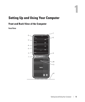
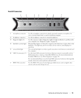
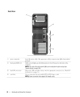
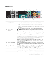
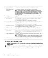
Back View 1 2 3 4 1 power connector 2 back panel LEDs (2) 3 back I/O connectors 4 card slots Insert the power cable. The appearance of this connector may differ from what is pictured. Multi-colored lights provide illumination for the I/O panel on the back of the computer. NOTE: The color of the back panel LEDs can be adjusted in system setup (see "System Setup" on page 132). Plug serial, USB, and other devices into the appropriate connectors (see "Back I/O Connectors" on page 17). Access connectors for any installed PCI or PCI Express cards. NOTE: Some connector slots support full-length cards. 16 Setting Up and Using Your Computer
-
 1
1 -
2
-
3
-
4
-
5
-
6
-
7
-
8
-
 9
9 -
 10
10 -
 11
11 -
 12
12 -
 13
13 -
 14
14 -
 15
15 -
 16
16 -
 17
17 -
 18
18 -
 19
19 -
20
-
21
-
22
-
23
-
24
-
25
-
26
-
27
-
28
-
29
-
30
-
31
-
32
-
33
-
34
-
35
-
36
-
37
-
38
-
39
-
40
-
41
-
42
-
43
-
44
-
45
-
46
-
47
-
48
-
49
-
50
-
51
-
52
-
53
-
54
-
55
-
56
-
57
-
58
-
59
-
60
-
61
-
62
-
63
-
64
-
65
-
66
-
67
-
68
-
69
-
70
-
71
-
72
-
73
-
74
-
75
-
76
-
77
-
78
-
79
-
80
-
81
-
82
-
83
-
84
-
85
-
86
-
87
-
88
-
89
-
90
-
91
-
92
-
93
-
94
-
95
-
96
-
97
-
98
-
99
-
100
-
101
-
102
-
103
-
104
-
105
-
106
-
107
-
108
-
109
-
110
-
111
-
112
-
113
-
114
-
115
-
116
-
117
-
118
-
119
-
120
-
121
-
122
-
123
-
124
-
125
-
126
-
127
-
128
-
129
-
130
-
131
-
132
-
133
-
134
-
135
-
136
-
137
-
138
-
139
-
140
-
141
-
142
-
143
-
144
-
145
-
146
-
147
-
148
-
149
-
150
-
151
-
152
-
153
-
154
-
155
-
156
-
157
-
158
-
159
-
160
-
161
-
162
-
163
-
164
-
165
-
166
-
167
-
168
-
169
-
170
-
171
-
172
-
173
-
174
 |
 |
16
Setting Up and Using Your Computer
Back View
1
3
4
2
1
power connector
Insert the power cable. The appearance of this connector may differ from what is
pictured.
2
back panel LEDs (2)
Multi-colored lights provide illumination for the I/O panel on the back of the
computer.
NOTE:
The color of the back panel LEDs can be adjusted in system setup (see
"System Setup" on page 132).
3
back I/O connectors
Plug serial, USB, and other devices into the
appropriate connectors
(see "Back I/O
Connectors" on page 17).
4
card slots
Access connectors for any installed PCI or PCI Express cards.
NOTE:
Some connector slots support full-length cards.