Dell XPS 8700 Owner's Manual - Page 68
Procedure, Postrequisites, Heat-Sink
 |
View all Dell XPS 8700 manuals
Add to My Manuals
Save this manual to your list of manuals |
Page 68 highlights
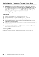
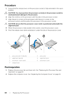
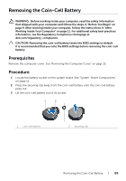
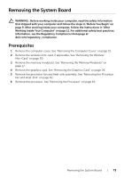
Procedure 1 Ensure that the release lever on the processor socket is fully extended in the open position. CAUTION: You must position the processor correctly in the processor socket to avoid permanent damage to the processor. 2 Align the notches on the processor with the tabs on the processor socket. 3 Align the pin-1 corner on the processor with the pin-1 corner on the processor socket, and then place the processor in the processor socket. CAUTION: Ensure that the processor-cover notch is positioned underneath the alignment post. 4 When the processor is fully seated in the socket, close the processor cover. 5 Pivot the release-lever down and place it under the tab on the processor cover. 1 3 2 6 4 5 7 1 processor pin-1 indicator 3 alignment tabs (2) 5 processor-cover notch 7 release lever 2 processor 4 alignment post 6 processor cover Postrequisites 1 Replace the processor fan and heat-sink. See "Replacing the Processor Fan and Heat-Sink" on page 64. 2 Replace the computer cover. See "Replacing the Computer Cover" on page 16. 68 | Replacing the Processor
-
 1
1 -
2
-
3
-
4
-
5
-
6
-
7
-
8
-
9
-
10
-
11
-
12
-
13
-
14
-
15
-
16
-
17
-
18
-
19
-
20
-
21
-
22
-
23
-
24
-
25
-
26
-
27
-
28
-
29
-
30
-
31
-
32
-
33
-
34
-
35
-
36
-
37
-
38
-
39
-
40
-
41
-
42
-
43
-
44
-
45
-
46
-
47
-
48
-
49
-
50
-
51
-
52
-
53
-
54
-
55
-
56
-
57
-
58
-
59
-
60
-
61
-
62
-
 63
63 -
 64
64 -
 65
65 -
 66
66 -
 67
67 -
 68
68 -
 69
69 -
 70
70 -
 71
71 -
 72
72 -
 73
73 -
74
-
75
-
76
-
77
-
78
-
79
-
80
-
81
-
82
-
83
-
84
-
85
-
86
 |
 |