Dewalt D28710 Instruction Manual - Page 10
Trigger Switch Fig. 1, Removal and Installation of Wheels, Fig. 1, 7, 8, Mounting Fig. 9, 10 - saw
 |
View all Dewalt D28710 manuals
Add to My Manuals
Save this manual to your list of manuals |
Page 10 highlights
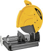
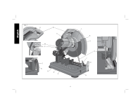
English Trigger Switch (Fig. 1) To start the tool, depress the trigger switch (N). To turn the tool off, release the trigger switch. Keep hands and material from wheel until it has coasted to a stop. To prevent unauthorized use of tool, install a standard padlock (not included) into the padlock hole (O) located in the trigger. Removal and Installation of Wheels (Fig. 1, 7, 8) WARNING: Turn off and unplug the tool before making any adjustments or removing or installing attachments or accessories. Be sure the trigger switch is in the OFF position. Do not make any adjustment while the wheel is in motion. Do not make any adjustment while chop saw is plugged into power supply. 1. Push in wheel lock lever (L) and rotate wheel (J) by hand until wheel lock lever engages slot in inside flange (S) to lock wheel. Loosen the bolt (T) counterclockwise in the center of the abrasive wheel with the 8mm hex wrench (G). Bolt has right-hand thread. 2. Remove the bolt (T), washer (U), outside flange (V) and old wheel (J). 3. Make sure flange surfaces are clean and flat. Install the new abrasive wheel by reversing the above steps. 4. Do not overtighten bolt. FIG. 7 WARNING: Check the work surface that the chop saw rests on when replacing with a new abrasive wheel. It is possible that the wheel may contact ANY ITEMS OR STRUCTURE THAT EXTENDS ABOVE work surface (under the base) when the arm is fully lowered. FIG. 8 J V T S U Mounting (Fig. 9, 10) CAUTION: Tool must be supported on stable, level, non-skid surface to prevent unexpected movement when operating. PROCEDURE FOR PERMANENT MOUNTING 1. Drill two holes 5/16" (8 mm) FIG. 9 through the work surface (Fig. 9). 2. Insert 1/4-20 screws down through the holes in the base and through holes in mounting surface. The approximate length of the screws should be the thickness of the mounting surface plus 4" (102 mm). 3. Tighten both screws securely. L 8
-
 1
1 -
2
-
3
-
4
-
 5
5 -
 6
6 -
 7
7 -
 8
8 -
 9
9 -
 10
10 -
 11
11 -
 12
12 -
 13
13 -
 14
14 -
 15
15 -
16
-
17
-
18
-
19
-
20
-
21
-
22
-
23
-
24
-
25
-
26
-
27
-
28
-
29
-
30
-
31
-
32
-
33
-
34
-
35
-
36
-
37
-
38
-
39
-
40
-
41
-
42
-
43
-
44
 |
 |
