Dewalt D28710 Instruction Manual - Page 9
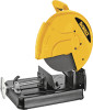
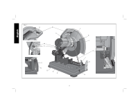
Vise Operation Fig. 4, Fence Operation, Depth Stop Fig. 1
 |
View all Dewalt D28710 manuals
Add to My Manuals
Save this manual to your list of manuals |
Page 9 highlights
English Vise Operation (Fig. 4) The vise (F) has a quick-travel feature. To release the vise when it is clamped tightly, turn the crank (H) counterclockwise one or two times to remove clamping pressure. Lift vise lever (I) up. Pull crank assembly out as far as desired. Vise may be pushed forward into work without cranking. Lower vise lever (I) then tighten vise (F) on work by using crank (H). Fence Operation WARNING: Turn off and unplug the tool before making any adjustments or removing or installing attachments or accessories. Be sure the trigger switch is in the OFF position. The fence (E) can be adjusted two ways: to change desired cutting angle and to change spacing between the fence and vise. TO CHANGE THE DESIRED CUTTING ANGLE (FIG. 5, 6) Use the wrench provided to loosen (do not remove) the two fence bolts (Q). Align the desired angle indicator line with the slot line (R) in the base (D). Securely tighten both fence bolts before use. FIG. 5 G Q D F R E For more accurate square cuts, disconnect the power supply, loosen the two fence bolts, push arm down until wheel extends into base. Place a square against the wheel and adjust fence against the square. Securely tighten both fence bolts before use. FIG. 6 Q J R E When making a miter cut, the vise (F) may not clamp securely, depending on the thickness of the workpiece and the miter angle. Other aids (such as spring, bar or C-clamps) will be necessary to secure the workpiece to the fence when making these cuts. TO CHANGE SPACING BETWEEN THE FENCE AND VISE Using the wrench provided, loosen and remove the two fence bolts (Q). Adjust the fence (E) to desired locations. Insert both fence bolts in provided locations. Securely tighten both fence bolts before use. Depth Stop (Fig. 1) Depth stop is set at the factory for a new 14" (355mm) wheel to prevent wheel from cutting into the supporting surface. To allow more depth of cut, use the 8mm hex wrench (G) provided to loosen the depth stop bolt (M) and raise bolt to desired height and then turn jam nut (P) clockwise until seated firmly on the casting. Securely tighten the depth stop bolt before use. CAUTION: When changing to a new wheel, readjust depth stop to original position to prevent cutting into supporting surface. 7
-
 1
1 -
2
-
3
-
 4
4 -
 5
5 -
 6
6 -
 7
7 -
 8
8 -
 9
9 -
 10
10 -
 11
11 -
 12
12 -
 13
13 -
 14
14 -
15
-
16
-
17
-
18
-
19
-
20
-
21
-
22
-
23
-
24
-
25
-
26
-
27
-
28
-
29
-
30
-
31
-
32
-
33
-
34
-
35
-
36
-
37
-
38
-
39
-
40
-
41
-
42
-
43
-
44
 |
 |
