Dewalt D51430 Instruction Manual - Page 3
Mise En Garde - stapler
 |
View all Dewalt D51430 manuals
Add to My Manuals
Save this manual to your list of manuals |
Page 3 highlights
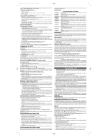
622540-00,01 D51430 3/24/04 10:50 AM Page 3 FIG. 2 FIG. 3 A E B C C D FIG. 4 FIG. 5 FIG. 6 FIG. 7 I F J LK • Avoid prolonged contact with dust from power sanding, sawing, grinding, drilling, and other construction activities. Wear protective clothing and wash exposed areas with soap and water. Allowing dust to get into your mouth, eyes, or lay on the skin may promote absorption of harmful chemicals. WARNING: Use of this tool can generate and/or disburse dust, which may cause serious and permanent respiratory or other injury. Always use NIOSH/OSHA approved respiratory protection appropriate for the dust exposure. Direct particles away from face and body. BEFORE OPERATING THIS TOOL, CAREFULLY READ AND UNDERSTAND ALL INSTRUCTIONS IN THE "IMPORTANT SAFETY INSTRUCTIONS" SECTION. ASSEMBLY CAUTION: Lock off trigger, disconnect air line from tool, and remove fasteners from magazine before making adjustments. Using the Lock-off (Fig. 5) WARNING: Always wear eye and ear protection when operating tool. Each DEWALT stapler is equipped with a trigger lock-off switch (F) which when rotated to the right, prevents the tool from actuating. When the switch is centered, the tool will be fully operational. The trigger should always be locked off whenever any adjustments are made or when tool is not in use. Trigger Examine your tool to determine which trigger is installed. However, the alternate trigger is included with the tool. For a replacement trigger contact your authorized service center or call 1-800-4-DEWALT. The gray trigger with imprinted on the side, (Cat.# D510022 kit) is the single sequential action trigger and causes the tool to operate in this mode. The black trigger with imprinted on the side, (Cat.# D510020 kit) is the bump action trigger and permits the tool to be actuated in this manner. For defining the use of the sequential action trigger and bump action trigger, see the Actuating Tool section of this manual. TRIGGER REMOVAL (FIG. 2) 1. Lock off trigger. 2. Remove air from the tool. 3. Remove rubber grommet (A) from end of dowel pin (B). 4. Remove dowel pin. 5. Remove trigger assembly from trigger cavity under the handle of the tool housing. TRIGGER INSTALLATION (FIG. 3) 1. Select either the sequential or bump trigger to be installed on the tool. Both triggers are included in the tool packaging. 2. Insert the trigger kit into trigger cavity. 3. Ensure that trigger spring (C) is placed around the trigger valve stem (E). 4. Align the holes of the trigger with the housing holes (D), then insert the dowel pin (B) through the entire assembly as shown. 5. Push the rubber grommet (A) onto the end of the dowel rod as shown. OPERATION Preparing the Tool 1. Read Safety Instruction section of this manual. 2. LUBRICATE TOOL (FIG. 4) a. Use DEWALT Pneumatic Tool Oil or a non-detergent S.A.E. 20 weight oil. DO NOT use detergent oil or additives as they will damage O-rings and rubber parts. b. Use a Filter and Regulator when possible. c. Add 5 to 7 drops of oil in the air fitting a least twice a day. 3. Wear eye and ear protection. 4. Ensure magazine is empty of all fasteners. 5. Check for smooth and proper operation of contact trip and pusher assemblies. Do not use tool if either assembly is not functioning properly. NEVER use a tool that has the contact trip restrained in the actuated position. 6. CHECK AIR SUPPLY: Ensure air pressure does not exceed recommended operating limits; 70 to 120 psi, (4.9 to 8.3 bar, 5 to 8.5 kg/cm2). 7. Keep tool pointed away from yourself and others. 8. Check that the trigger is locked off. 9. Connect air hose. 10. Check for audible leaks around valves and gaskets. Never use a tool that leaks or has damaged parts. Loading the Tool CAUTION: Keep tool pointed in a safe direction when loading fasteners. CAUTION: Never load fasteners with the contact trip or trigger activated. 1. Pull pusher back until it locks at the rear of the magazine. 2. Insert fasteners onto magazine rail. 3. Unlatch pusher and slide forward until pusher contacts fasteners. Actuating Tool WARNING: Always wear eye and ear protection when operating tool. The tool can be actuated using one of two modes: single sequential action trigger mode and bump action trigger mode. The trigger installed on the tool as described in the Trigger section of this manual determines the mode of operation. SEQUENTIAL ACTION TRIGGER - (GRAY) The sequential action trigger's intended use is for intermittent fastening where very careful and accurate placement is desired. To operate the stapler in sequential action mode: 1. Depress the contact trip firmly against the work surface. 2. Depress the trigger. CAUTION: A fastener will fire each time the trigger is depressed as long as the contact trip remains depressed. BUMP ACTION TRIGGER - (BLACK) The bump action trigger's intended use is for rapid fastening on flat, stationary surfaces. Using the bump action trigger, two methods are available: place actuation and bump actuation. To operate the tool using the PLACE ACTUATION method: 1. Depress the contact trip against the work surface. 2. Depress the trigger. To operate the tool using the BUMP ACTUATION method: 1. Depress the trigger. 2. Push the contact trip against the work surface. As long as the trigger is depressed, the tool will fire a fastener every time the contact trip is depressed. This allows the user to drive multiple fasteners in sequence. CAUTION: Do not keep trigger depressed when tool is not in use. Keep the lock-off switch rotated to the right (OFF) when the tool is not in use. Adjusting Depth (Fig. 6) The depth that the fastener is driven can be adjusted using the depth adjustment next to the trigger of the tool. WARNING: To reduce risk of serious injury from accidental actuation when attempting to adjust depth, ALWAYS: • Lock off trigger. • Disconnect air supply. • Depress and hold depth adjustment lock button (I) before sliding depth adjustment bar (J). • Avoid contact with trigger during adjustments. 1. To drive the fastener shallower, press the lock button and slide the depth adjustment bar downward to the extent desired using the adjustment marks. Release the lock button. 2. To sink a fastener deeper, press the lock button and slide the depth adjustment bar upward to the extent desired using the adjustment marks. Release the lock button. Clearing a Jammed Fastener (Fig. 7) If a fastener becomes jammed in the nosepiece, keep the tool pointed away from you and follow these instructions to clear: 1. Lock off trigger. 2. Disconnect air supply from tool. 3. Release pusher from behind fasteners. 4. Push down front latch (K) then pull up to open front door (L). 5. Remove bent fastener, using pliers if necessary. 6. If driver blade is in the down position, insert screwdriver or other rod into nosepiece and push driver blade back in position. 7. Remove rod and close front door. 8. Lift latch to secure door to nosepiece. 9. Reattach air supply. 10. Reinsert fasteners into magazine (see Loading the Tool). 11. Release pusher. NOTE: Should fasteners continue to jam frequently in nosepiece, have tool serviced by an authorized DEWALT service center. Cold Weather Operation When operating tools at temperatures below freezing: 1. Make sure compressor tanks have been properly drained prior to use. 2. Keep tool as warm as possible prior to use. 3. Make certain all fasteners have been removed from magazine. 4. Put 5 to 10 drops of DEWALT Pneumatic Tool Oil in the air inlet. 5. Lower air pressure to 80 psi or less. 6. Reconnect air and and load fasteners into magazine. 7. Actuate the tool 5 or 6 times into scrap lumber to lubricate O-rings. 8. Turn pressure up to operating level (not to exceed 120 psi) and use tool as normal. 9. Re-lubricate at least once daily. 10. Always drain the compressor tanks at least once a daily. Hot Weather Operation Tool should operate normally. However, keep tool out of direct sunlight as excessive heat can deteriorate bumpers, O-rings and other rubber parts resulting in increased maintenance. MAINTENANCE Daily Maintenance Chart ACTION Lubricate tool with 5-7 drops of DEWALT Pneumatic Tool Oil WHY Prevents failure of O-rings. HOW Insert drops into air fitting on end cap of tool. ACTION Drain compressor tanks and hoses daily. WHY Prevents accumulation of moisture in compressor and stapler. HOW Open petcocks or other drain valves on compressor tanks. Allow any accumulated water to drain from hoses. ACTION Clean magazine, pusher, and contact trip mechanism. WHY Permits smooth operation of magazine, reduces wear, and prevents jams. HOW Blow clean with compressor air. The use of oils, lubricants periodically or solvents is not recommended as they tend to attract debris. ACTION Before each use, check to insure all screws, nuts and fasteners are tight and undamaged. WHY Prevents jams, leaks and premature failure of tool parts. HOW Tighten loose screws or other fasteners using the appropriate Allen wrench or screwdriver. Repairs To assure product SAFETY and RELIABILITY, repairs, maintenance and adjustment should be performed by authorized service centers or other qualified service personnel, always using identical replacement parts. Refer to the Troubleshooting Guide at the end of this section. Accessories Recommended accessories for use with your tool are available for purchase from your local dealer or authorized service center. If you need assistance in locating any accessory for your tool, contact: DEWALT Industrial Tool Co., 701 East Joppa Road, Baltimore, MD 21286 (1-8004-DEWALT). WARNING: The use of any other accessory not recommended for use with this tool could be hazardous. Three Year Limited Warranty DEWALT will repair, without charge, any defects due to faulty materials or workmanship for three years from the date of purchase. This warranty does not cover part failure due to normal wear or tool abuse. For further detail of warranty coverage and warranty repair information, visit www.dewalt.com or call 1-800-4-DEWALT (1-800-433-9258). This warranty does not apply to accessories or damage caused where repairs have been made or attempted by others. This warranty gives you specific legal rights and you may have other rights which vary in certain states or provinces. In addition to the warranty, DEWALT tools are covered by our: 1 YEAR FREE SERVICE DEWALT will maintain the tool and replace worn parts caused by normal use, for free, any time during the first year after purchase. Nailer wear items, such as O-rings and driver blades, are not covered. 90 DAY MONEY BACK GUARANTEE If you are not completely satisfied with the performance of your DEWALT Power Tool, Laser, or Nailer for any reason, you can return it within 90 days from the date of purchase with a receipt for a full refund - no questions asked. FREE WARNING LABEL REPLACEMENT: If your warning labels (Fig. 8) become illegible or are missing, call 1-800-4-DEWALT for a free replacement. Français (suite) • verrouiller la gâchette en position d'arrêt; • débrancher l'outil du circuit d'alimentation en air; • maintenir le bouton de verrouillage de réglage de profondeur (fig. T1) enfoncé en faisant glisser la barre coulissante de réglage de profondeur (fig. T2); • éviter tout contact avec la gâchette lors des réglages (fig. U). • Ne pas enfoncer des attaches au hasard dans les murs, les planchers ou toute autre surface de travail; les attaches pourraient percer des fils sous tension, des tuyaux ou tout autre obstacle et causer ainsi des blessures. (fig. V) • Rester vigilant en tout temps et faire preuve de jugement lorsqu'on utilise un outil électrique; ne pas utiliser l'outil lorsqu'on est fatigué ou sous l'influence de drogues, d'alcool ou de médicaments; un moment d'inattention pourrait entraîner des blessures graves. AVERTISSEMENT : L'utilisation de ce produit augmente les risques d'exposition à des produits chimiques qui, dans l'État de la Californie, sont reconnus comme étant susceptibles de causer le cancer, d'entraîner des malformations congénitales ou d'être nocifs pour le système reproductif. Éviter d'inhaler les vapeurs et les poussières environnantes. Se laver les mains après chaque utilisation. • Éviter tout contact prolongé avec la poussière soulevée par cet outil ou autres outils électriques. Porter des vêtements de protection et nettoyer les parties exposées du corps à l'eau savonneuse. S'assurer de bien se protéger afin d'éviter d'absorber par la bouche, les yeux ou la peau des produits chimiques nocifs. AVERTISSEMENT : Cet outil peut produire et répandre de la poussière susceptible de causer des dommages sérieux et permanents au système respiratoire. Toujours utiliser un appareil respiratoire anti-poussières approprié approuvé par le NIOSH ou l'OSHA. Diriger les particules dans le sens opposé du visage et du corps. AVANT D'UTILISER L'OUTIL, LIRE ATTENTIVEMENT ET COMPRENDRE TOUTES LES DIRECTIVES INDIQUÉES À LA SECTION « IMPORTANTES CONSIGNES DE SÉCURITÉ ». ASSEMBLAGE MISE EN GARDE : Verrouiller la gâchette en position d'arrêt et débrancher l'outil du circuit d'alimentation en air, puis retirer les attaches du chargeur avant d'effectuer un réglage. Utilisation du bouton de verrouillage en position d'arrêt (fig. 5) AVERTISSEMENT : Toujours porter des lunettes de protection et des protecteurs auditifs durant l'utilisation. Chaque agrafeuse DEWALT est munie d'un interrupteur à gâchette. Pour verrouiller l'outil en position d'arrêt (F), tourner l'interrupteur vers la droite; pour le mettre en marche, placer l'interrupteur au centre. La gâchette doit toujours être verrouillée en position d'arrêt lorsqu'on effectue un réglage ou après chaque utilisation. Gâchette Examiner l'outil afin de déterminer laquelle des deux gâchettes y est installée (les deux gâchettes sont fournies avec l'outil). Pour obtenir des gâchettes de rechange, communiquer avec le centre de service autorisé le plus près ou appeler DEWALT directement en composant le 1 800 433-9258 (1-800-4-DEWALT). La gâchette grise pour le mode de fonctionnement séquentiel simple comporte une étiquette « » représentant une seule attache sur le côté (no de catalogue D510022). Elle sert à actionner l'outil selon ce mode de fonctionnement. La gâchette noire pour le mode de fonctionnement saccadé comporte une étiquette « » représentant plusieurs attaches sur le côté (no de catalogue D510020). Elle sert à actionner l'outil selon ce mode de fonctionnement.
-
 1
1 -
 2
2 -
 3
3 -
 4
4 -
 5
5 -
 6
6 -
 7
7
 |
 |
