Dewalt DCGG571M1 Instruction Manual - Page 12
Save These Instructions, For Future Use, Components Fig. 2, 5
 |
View all Dewalt DCGG571M1 manuals
Add to My Manuals
Save this manual to your list of manuals |
Page 12 highlights
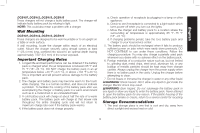
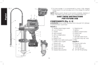
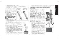
English FIG. 2 G R V H NR I J K L U ED F T B A C Q P O M 2. For long storage, it is recommended to store a fully charged battery pack in a cool dry place out of the charger for optimal results. NOTE: Battery packs should not be stored completely depleted of charge. The battery pack will need to be recharged before use. SAVE THESE INSTRUCTIONS FOR FUTURE USE COMPONENTS (Fig. 2, 5) WARNING: Never modify the power tool or any part of it. Damage or personal injury could result. FIGURE 2 A. Variable speed trigger switch O. Retaining slot B. Lock-off button P. Battery C. Handle Q. Battery release button D. LED worklight R. Rubber feet E. LED worklight button S. Hose clip F. Top cap T. Shoulder strap mount G. Flexible hose U. Shoulder strap clip holes H. Flexible hose safety spring guard V. Filter I. Flexible hose coupler FIGURE 5 J. Grease tube W. Pressure relief valve K. Grease tube cap X Purge valve L. Grease tube handle Y. Check valve M. Grease tube rod S N. Grease tube assembly Z. 1/8" NPT fill port AA. 1/8" NPT fill port plug 10
-
 1
1 -
2
-
3
-
4
-
5
-
6
-
 7
7 -
 8
8 -
 9
9 -
 10
10 -
 11
11 -
 12
12 -
 13
13 -
 14
14 -
 15
15 -
 16
16 -
 17
17 -
18
-
19
-
20
-
21
-
22
-
23
-
24
-
25
-
26
-
27
-
28
-
29
-
30
-
31
-
32
-
33
-
34
-
35
-
36
-
37
-
38
-
39
-
40
-
41
-
42
-
43
-
44
-
45
-
46
-
47
-
48
-
49
-
50
-
51
-
52
-
53
-
54
-
55
-
56
-
57
-
58
-
59
-
60
-
61
-
62
-
63
-
64
-
65
-
66
-
67
-
68
 |
 |
