Dewalt DCS371P1 Instruction Manual - Page 13
ASSEMBLY AND, ADJUSTMENTS, Installing and Removing the Battery Pack Fig. 1, 2, 4 - blade
 |
View all Dewalt DCS371P1 manuals
Add to My Manuals
Save this manual to your list of manuals |
Page 13 highlights
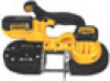
English 3. Use a 3 mm hex wrench (E) to turn one of the FIG. 3 tracking screws (O) 1/4 turn clockwise. Turn K D A the other tracking screw 1/4 turn clockwise. NOTE: Turning the tracking screw clockwise P moves the blade toward the guide roller, turning the tracking screw counterclockwise moves the blade away from the guide roller. Q 4. Tighten both the adjusting locking nuts and M close the quick release lever. (It will be necessary J to run the saw to observe the tracking.) 5. Observe blade tracking between runs and repeat Steps 1-4 as necessary to achieve proper blade tracking. ASSEMBLY AND ADJUSTMENTS J WARNING: To reduce the risk of serious personal injury, turn tool off and remove the L battery pack before making any adjustments or removing/installing attachments or accessories. An accidental start-up can cause injury. N F G L N FIG. 4 Installing and Removing the Battery Pack (Fig. 1, 2, 4) NOTE: For best results, make sure your battery pack is fully charged. To install the battery pack (P) into the tool handle, align the battery pack with the rails inside the tool's handle and slide it into the handle until the battery pack is firmly seated in the tool and ensure that it does not disengage. To remove the battery pack from the tool, press the release button (Q) and firmly pull the battery pack out of the tool handle. Insert it into the charger as described in the charger section of this Q manual. 11
-
 1
1 -
2
-
3
-
4
-
5
-
6
-
7
-
 8
8 -
 9
9 -
 10
10 -
 11
11 -
 12
12 -
 13
13 -
 14
14 -
 15
15 -
 16
16 -
 17
17 -
 18
18 -
19
-
20
-
21
-
22
-
23
-
24
-
25
-
26
-
27
-
28
-
29
-
30
-
31
-
32
-
33
-
34
-
35
-
36
-
37
-
38
-
39
-
40
-
41
-
42
-
43
-
44
-
45
-
46
-
47
-
48
-
49
-
50
-
51
-
52
-
53
-
54
-
55
-
56
-
57
-
58
-
59
-
60
-
61
-
62
-
63
-
64
 |
 |
