EVGA 123-LF-E653-KR User Guide
EVGA 123-LF-E653-KR - P55 LE Motherboard Manual
 |
UPC - 843368011697
View all EVGA 123-LF-E653-KR manuals
Add to My Manuals
Save this manual to your list of manuals |
EVGA 123-LF-E653-KR manual content summary:
- EVGA 123-LF-E653-KR | User Guide - Page 1
User's Guide EVGA P55 LE Motherboard - EVGA 123-LF-E653-KR | User Guide - Page 2
- EVGA 123-LF-E653-KR | User Guide - Page 3
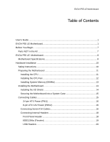
's Guide ...1 EVGA P55 LE Motherboard 1 Before You Begin...7 Parts NOT in the Kit 7 EVGA P55 LE Motherboard 8 Motherboard Specifications 8 Hardware Installation 10 Safety Instructions 10 Preparing the Motherboard 11 Installing the CPU 11 Installing the CPU Fan 12 Installing System Memory - EVGA 123-LF-E653-KR | User Guide - Page 4
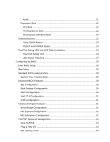
LED Status Indicators 24 Configuring the BIOS 25 Enter BIOS Setup 26 Main Menu...26 Standard BIOS Features Menu 28 System Time / System Date 29 Advanced BIOS Features 29 IDE Configuration 30 Boot Settings Configuration 30 AHCI Configuration 30 Intel VT-d Configuration 31 USB Configuration - EVGA 123-LF-E653-KR | User Guide - Page 5
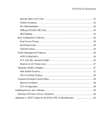
37 Hardware Health Configure 37 H/W Health Function 37 CPU Fan Mode Setting 38 Frequency/Voltage Control Menu 38 Memory Configure 38 CPU Configuration 38 Installing Drivers and Software 39 Windows XP/Vista/7 Driver Installation 39 Appendix A. POST Codes for the EVGA P55 LE Motherboard 40 - EVGA 123-LF-E653-KR | User Guide - Page 6
List of Figures Figure 1. PW1 Motherboard Connector 16 Figure 2. CMOS Setup Utility Main Menu 27 Figure 3. Standard BIOS Features Menu 28 Figure 4. Advanced BIOS Features 30 Figure 5. Advanced Chipset Features 31 Figure 6. PCI/PNP Resource Management 33 Figure 7. Boot Configuration Features - EVGA 123-LF-E653-KR | User Guide - Page 7
all the hardware necessary to install and connect your new EVGA P55 LE Motherboard. However, it does not contain the following items that must be purchased separately to make the motherboard functional. Intel Socket 1156 Processor DDR3 System Memory Socket 1156 or Socket 775 Cooling fan PCI - EVGA 123-LF-E653-KR | User Guide - Page 8
EVGA P55 LE Motherboard Motherboard Specifications Size ATX form factor of 12 inch x 9.6 inch Processor support Intel Socket 1156 CPU's Operating systems: Supports Windows XP 32bit/64bit, Windows Vista 32bit/64bit, and Windows 7 32bit/64bit Intel P55 Express Chipset System Memory support - EVGA 123-LF-E653-KR | User Guide - Page 9
Audio Realtek High-Definition audio Supports 8-channel audio Supports S/PDIF output (Optical and COAX) Supports Jack-Sensing function Green Function Supports ACPI (Advanced Configuration and Power Interface) Supports S0 (normal), S1 (power on suspend), S3 (suspend to RAM), S4 (Suspend to disk - EVGA 123-LF-E653-KR | User Guide - Page 10
This section will guide you through the installation of the motherboard. The topics covered in this section are: Preparing the motherboard Installing the CPU Installing the CPU fan Installing the memory Installing the motherboard Connecting cables Safety Instructions To reduce the - EVGA 123-LF-E653-KR | User Guide - Page 11
Preparing the Motherboard Installing the CPU Be very careful when handling the CPU. Hold the processor only by the edges and do not touch the contacts on the motherboard or CPU. Any physical damage to the motherbard pins will void the warranty. Use the following procedure to install the CPU onto the - EVGA 123-LF-E653-KR | User Guide - Page 12
Load plate tip under screw cap Installing the CPU Fan There are many different fan types that can be used with this motherboard. Follow the instruction that came with you fan assembly. Be sure that the fan orientation is correct for your chassis type and your fan assembly. Please note that - EVGA 123-LF-E653-KR | User Guide - Page 13
new motherboard has four 240-pin slots for DDR3 memory. These slots support 1GB, 2GB, 4GB DDR3 technologies. There must be at least one memory bank populated to ensure normal operation. Use the following the recommendations for installing memory. One DIMM: If using 1 DIMM (Single Channel), install - EVGA 123-LF-E653-KR | User Guide - Page 14
Installing the I/O Shield The motherboard kit comes with an I/O shield that is used to block radio frequency transmissions, protects internal components from dust and foreign objects, and promotes correct airflow within the chassis. Before installing the motherboard, install the I/O shield from the - EVGA 123-LF-E653-KR | User Guide - Page 15
the connectors to the I/O shield. 4. Ensure that the fan assembly is aligned with the chassis vents according to the fan assembly instruction. 5. Secure the motherboard with a recommended minimum of nine (9) screws. Connecting Cables This section takes you through all the necessary connections on - EVGA 123-LF-E653-KR | User Guide - Page 16
until seated. Connecting Serial ATA Cables The Serial ATA II connector is used to connect the Serial ATA II device to the motherboard. These connectors support the thin Serial ATA II cables for - EVGA 123-LF-E653-KR | User Guide - Page 17
serial ATA connectors on this motherboard. These connections are designed to be angled to not interfere with any expansions cards. These connection points support RAID 0, RAID 1, and RAID 10 configurations. SATA 4 (bottom) SATA 2 (bottom) SATA 0 (bottom) SATA 5 (top) SATA 3 (top) SATA 1 (top - EVGA 123-LF-E653-KR | User Guide - Page 18
Connecting Internal Headers Front Panel Header The front panel header on this motherboard is one connector used to connect the following four cables. (see Table 2 for pin definitions): PWRLED Attach the front panel power LED cable to these two pins of the connector. The Power LED indicates the - EVGA 123-LF-E653-KR | User Guide - Page 19
IEEE1394a (Firewire) This motherboard has one IEEE 1394a onboard header. Alternatively, you can also connect this to your system case (if applicable). 1. Secure the bracket to either the front or rear panel of the system case (not all system cases are equipped with the front panel option). Connect - EVGA 123-LF-E653-KR | User Guide - Page 20
USB Headers This motherboard contains seven (7) USB 2.0 ports that are exposed on the rear panel of the chassis (Figure 2). The motherboard also contains three (3) 10pin internal header connectors onboard that can be used to connect an optional external bracket containing up to six (6) USB 2.0 ports - EVGA 123-LF-E653-KR | User Guide - Page 21
HD audio standard and provides two kinds of audio output choices: the Front Audio, the Rear Audio. The front Audio supports re-tasking function. Table 5. Front Audio Connector Connector Front Audio Connector 10 9 8 7 6 5 4 3 2 1 Pin Signal 1 PORT1_L 2 AUD_GND 3 PORT1_R 4 PRECENCE_J - EVGA 123-LF-E653-KR | User Guide - Page 22
slot that is designed to accommodate PCIe x1 cards, such as an EVGA Killer Xeno Network Card or Sound Card. The x1 slot provides 250 Cards and PCI Express x1 and x4 devices. The design of this motherboard supports multiple Graphic Card technology. When installing a PCI Express Graphic Card, be sure - EVGA 123-LF-E653-KR | User Guide - Page 23
or clear the CMOS. Clear CMOS Button The motherboard uses the CMOS RAM to store all the set parameters. The CMOS can be cleared by pressing These buttons allow for easy debugging and testing of the system during troubleshooting situations. The POWER button with LED indicates the system's status. - EVGA 123-LF-E653-KR | User Guide - Page 24
the system may be failing to boot. It is useful during troubleshooting situations. This Debug LED will also display current CPU temperatures after the System is powered on: This LED is on. DIMM LED (Orange): When the Memory slot is functional: This LED is on. STANDBY LED (Blue): When the System - EVGA 123-LF-E653-KR | User Guide - Page 25
how to change the system settings through the BIOS Setup menus. Descriptions of the BIOS parameters are also provided. This section includes the following information: Enter BIOS Setup Main Menu Standard BIOS Features Advanced BIOS Features Advanced Chipset Features PCI/PnP Resource - EVGA 123-LF-E653-KR | User Guide - Page 26
to Load Defaults, DEL to enter Setup. Pressing Del takes you to the AMI BIOS CMOS Setup Utility. Main Menu The main menu allows you to select from the Copyright (C) 1985-2005, American Megatrends Standard BIOS Features Advanced BIOS Features Advanced Chipset Features PCI/PNP Resource - EVGA 123-LF-E653-KR | User Guide - Page 27
menu to set up the basic system configuration. Advanced BIOS Features Use this menu to set up the advanced system /Voltage Control Use this menu to optimize system performance and configure clocks, voltages, memory timings, and more. Load Optimal Defaults Load default system settings. Discard - EVGA 123-LF-E653-KR | User Guide - Page 28
:08.00.16 Build Date:07/16/10 ID :1E655000 Processor Intel(R) Core(TM) CPU Speed :2666MHz Count :1 750 @ 2.67GHz Help Item Use [ENTER] , [TAB] Or [SHIFT-TAB] to select a field. Use [+] or [-] to Configure system Time. System Memory Size :4088MB System Time System Date [13:37:00] [Fri - EVGA 123-LF-E653-KR | User Guide - Page 29
Configuring the BIOS System Time / System Date Using the arrow keys, position the cursor [13:37:00] [Fri 07/16/2010] Time (hh:mm:ss) 14 : 48: 43 Advanced BIOS Features Access the Advanced BIOS Features menu from the CMOS Setup Utility screen. Use the + and - keys to scroll through the options - EVGA 123-LF-E653-KR | User Guide - Page 30
Boot Device Priority Move Enter:Select +/-/:Value F10:Save ESC:Exit F1:General Help F5:Previous Values F7:Optimized Defaults Figure 4. Advanced BIOS Features IDE Configuration Use this to configure your storage drivers and to enable RAID or switch between IDE and AHCI mode. Please note - EVGA 123-LF-E653-KR | User Guide - Page 31
Configuring the BIOS USB Configuration This option menu allows you to enable Legacy USB support, force USB 1.1 mode and North Bridge Configuration [Press Enter] PCI Express Configuration [Press Enter] Intel VT-d [Disabled] HD Audio Controller [Enabled] IEEE1394 [Enabled] LAN1 Controller - EVGA 123-LF-E653-KR | User Guide - Page 32
such as Payload size. It is not recommended to adjust these settings. Intel VT-d Configuration This option menu allows you to enable, or disable, this enabled, unless you are using an external Network Controller, such as an EVGA Killer Xeno card. PE1 Slot This function allows you to enable or - EVGA 123-LF-E653-KR | User Guide - Page 33
Figure 6. PCI/PNP Resource Management Clear NVRAM This function clears the NVRAM during System Boot. Plug & Play O/S This function sets whether the O/S or BIOS configures Plug and Play devices. A setting of [No] is default. PCI Latency Timer This function sets the value in units of PCI clocks. - EVGA 123-LF-E653-KR | User Guide - Page 34
PCI IDE BusMaster This function allows the BIOS to use PCI BusMastering for reading or writing to IDE drives. OffBoard PCI/ISA IDE Card This function allows manual override of PCI/ISA external cards. be used by PCI/PnP devices. Reserved Memory Size This option allows you to specify the size of the - EVGA 123-LF-E653-KR | User Guide - Page 35
Boot Configuration Features Select Boot Configuration Features from the CMOS Setup Utility menu and press Enter to display the settings. Boot Device Priority Hard Disk Drives CD/DVD Drives [Press Enter] [Press Enter] [Press Enter] Help Item Specifies the Boot Device Priority sequence. - EVGA 123-LF-E653-KR | User Guide - Page 36
CD/DVD Drives This option menu allows you specification of the CD/DVD boot priority sequence. Power Management Features Select Power Management Features from the CMOS Setup Utility menu and press Enter to display the settings. Power Management Features ACPI Configuration [Press Enter] - EVGA 123-LF-E653-KR | User Guide - Page 37
Configuring the BIOS Restore on AC Power Loss This menu allows adjustment of the AC :48C/118F :34C/93F CPU Fan Speed Power Fan Speed Chassis Fan Speed :3264 RPM :1337 RPM :3864 RPM VCore Memory CPU VTT PCH +5V :1.337 V :1.481 V :1.021 V :1.031 V :4.961 V Help Item Enables Hardware Health - EVGA 123-LF-E653-KR | User Guide - Page 38
settings. Phoenix - AwardBIOS CMOS Setup Utility Frequency/Voltage Control Memory Configure CPU Configuration [Press Enter] [Press Enter] CPU Setting CPU Frequency Setting PCIE Frequency Setting [20] [133] [100] EVGA VDroop Control [With VDroop] Current CPU VCore : 1.33700V CPU VCore - EVGA 123-LF-E653-KR | User Guide - Page 39
with the EVGA P55 LE Motherboard contains the following software and drivers: Chipset Drivers Audio drivers LAN Drivers RAID Drivers EVGA E-LEET Overclocking Utility Adobe Acrobat Reader User's Manual Windows XP/Vista/7 Driver Installation 5. Insert the Intel P55 installation CD - EVGA 123-LF-E653-KR | User Guide - Page 40
provides the AMI POST Codes (Table 6) for the EVGA P55 LE Motherboard during system boot up. The POST Codes are C1 C2 C5 C6 C7 0A 0B 0C 0E 13 AMI POST Code Description Initialize BIOS. Check Battery Power and CMOS Initialize interrupt controlling hardware/vector table Initialize system timer Fixes - EVGA 123-LF-E653-KR | User Guide - Page 41
A2 A4 A7 A9 Description Relocate System Management interrupt vector Uncompress and initialize BIOS module Initialize devices primary Initialize devices secondary Initialize output devices Allocate memory for ADM module Initialize silent boot module Display sign-on message Initialize USB controller - EVGA 123-LF-E653-KR | User Guide - Page 42
CPU Temp (if enabled) EVGA Glossary of Terms ACPI - Advanced Configuration and Power Interface AFR - Alternate Frame Rendering APIC - Advanced Programmable Interrupt Controller BIOS - Basic Input Output System CD-ROM - Compact Disc Read-Only Memory CMOS - Complementary Metal-Oxide Semiconductor - EVGA 123-LF-E653-KR | User Guide - Page 43
PCI - Peripheral Component Interconnect PCIe - Peripheral Component Interconnect Express PCI-x - Peripheral Component Interconnect Extended POST - Power on Self Test PWM - Pulse Width Modulation Configuring the BIOS - EVGA 123-LF-E653-KR | User Guide - Page 44
RGB - Red Green Blue SATA - Serial Advanced Technology Attachment SB - Southbridge SCSI - Small Computer System Interface SFR - Split Frame Rendering SLI - Scalable Link Interface SPD - Serial Presence Detect SPDIF - Sony/Philips Digital Interconnect Format SPP - System Platform Processors TCP/IP
-
 1
1 -
 2
2 -
 3
3 -
 4
4 -
 5
5 -
 6
6 -
 7
7 -
8
-
9
-
10
-
11
-
12
-
13
-
14
-
15
-
16
-
17
-
18
-
19
-
20
-
21
-
22
-
23
-
24
-
25
-
26
-
27
-
28
-
29
-
30
-
31
-
32
-
33
-
34
-
35
-
36
-
37
-
38
-
39
-
40
-
41
-
42
-
43
-
44
 |
 |

User
’s
Guide
EVGA P55 LE Motherboard