EVGA 123-LF-E653-KR User Guide - Page 20
USB Headers
 |
UPC - 843368011697
View all EVGA 123-LF-E653-KR manuals
Add to My Manuals
Save this manual to your list of manuals |
Page 20 highlights
USB Headers This motherboard contains seven (7) USB 2.0 ports that are exposed on the rear panel of the chassis (Figure 2). The motherboard also contains three (3) 10pin internal header connectors onboard that can be used to connect an optional external bracket containing up to six (6) USB 2.0 ports. 1. Secure the bracket to either the front or rear panel of your chassis (not all chassis are equipped with the front panel option). 2. Connect the end of the cable(s) to the USB 2.0 header on the motherboard. Table 4. USB 2.0 Header Pins Connector Pin USB 2.0 Header Connector 1 3 5 7 9 Pin 2 4 6 8 10 Signal 5V_DUAL DD+ GND Empty Signal 5V_DUAL DD+ GND No Connect
-
 1
1 -
2
-
3
-
4
-
5
-
6
-
7
-
8
-
9
-
10
-
11
-
12
-
13
-
14
-
 15
15 -
 16
16 -
 17
17 -
 18
18 -
 19
19 -
 20
20 -
 21
21 -
 22
22 -
 23
23 -
 24
24 -
 25
25 -
26
-
27
-
28
-
29
-
30
-
31
-
32
-
33
-
34
-
35
-
36
-
37
-
38
-
39
-
40
-
41
-
42
-
43
-
44
 |
 |

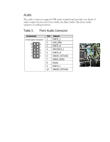
USB Headers
This motherboard contains seven (7) USB 2.0
ports that are exposed on the rear panel of the chassis
(Figure 2). The motherboard also contains three (3) 10-
pin internal header connectors onboard that can be used
to connect an optional external bracket containing up to
six (6) USB 2.0 ports.
1.
Secure the bracket to either the front or rear panel
of your chassis (not all chassis are equipped with the
front panel option).
2.
Connect the end of the cable(s) to the USB 2.0
header on the motherboard.
Table 4.
USB 2.0 Header Pins
Connector
Pin
Signal
USB 2.0 Header Connector
1
5V_DUAL
3
D-
5
D+
7
GND
9
Empty
Pin
Signal
2
5V_DUAL
4
D-
6
D+
8
GND
10
No Connect