Electrolux E30DF74GPS Installation Instructions
Electrolux E30DF74GPS - 30" Pro-Style Dual-Fuel Range Manual
 |
View all Electrolux E30DF74GPS manuals
Add to My Manuals
Save this manual to your list of manuals |
Electrolux E30DF74GPS manual content summary:
- Electrolux E30DF74GPS | Installation Instructions - Page 1
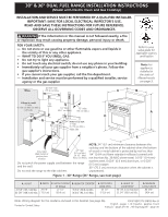
30" & 36" DUAL FUEL RANGE INSTALLATION INSTRUCTIONS (Model with Electric Oven and Gas Cooktop) INSTALLATION AND SERVICE MUST BE PERFORMED BY A QUALIFIED INSTALLER. IMPORTANT: SAVE FOR LOCAL ELECTRICAL INSPECTOR'S USE. READ AND SAVE THESE INSTRUCTIONS FOR FUTURE REFERENCE. OBSERVE ALL GOVERNING - Electrolux E30DF74GPS | Installation Instructions - Page 2
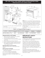
30" & 36" DUAL FUEL RANGE INSTALLATION INSTRUCTIONS (Model with Electric Oven and Gas Cooktop) WALL 35 7/8" Min. (91.1 cm Min.) C B WALL If there is a wall: 9" Min. (22.9 cm Min) Left side See note 18" Min. (45.7 - Electrolux E30DF74GPS | Installation Instructions - Page 3
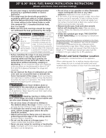
30" & 36" DUAL FUEL RANGE INSTALLATION INSTRUCTIONS (Model with Electric Oven and Gas Cooktop) • Be sure your range is installed and grounded properly by a qualified installer or service technician. • This range must be electrically grounded in accordance with local codes or, in their absence, with - Electrolux E30DF74GPS | Installation Instructions - Page 4
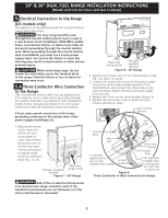
30" & 36" DUAL FUEL RANGE INSTALLATION INSTRUCTIONS (Model with Electric Oven and Gas Cooktop) 2. Factory Connected Power Supply Cord (Canada only) Your range is equipped with a factory-connected power cord (see Figure 3). Cord must be connected to a grounded 120/240 volt or 120/208 volt range - Electrolux E30DF74GPS | Installation Instructions - Page 5
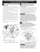
30" & 36" DUAL FUEL RANGE INSTALLATION INSTRUCTIONS (Model with Electric Oven and Gas Cooktop) 5. Electrical Connection to the Range (US models only) This appliance is manufactured with the neutral terminal connected to the range. You may not ground the oven through the neutral (white) wire if oven - Electrolux E30DF74GPS | Installation Instructions - Page 6
30" & 36" DUAL FUEL RANGE INSTALLATION INSTRUCTIONS (Model with Electric Oven and Gas Cooktop) 5.B Four Conductor Wire Connection to the Range 1. Remove the screws at the lower end of the rear wire access cover or panel, then remove the access cover or lift the lower part of the access panel to - Electrolux E30DF74GPS | Installation Instructions - Page 7
30" & 36" DUAL FUEL RANGE INSTALLATION INSTRUCTIONS (Model with Electric Oven and Gas Cooktop) 6.B Four Conductor Wire Connection to the Junction Box If oven is used in a new branch circuit installation (1996 NEC), mobile home, recreational vehicle, or where local codes do not permit connecting the - Electrolux E30DF74GPS | Installation Instructions - Page 8
30" & 36" DUAL FUEL RANGE INSTALLATION INSTRUCTIONS (Model with Electric Oven and Gas Cooktop) 8. Gas Supply Installation When shipped from the factory, this unit is designed to operate on 4"(10,16 cm) water column (1.0 kPa) Natural gas manifold pressure. A convertible pressure regulator - Electrolux E30DF74GPS | Installation Instructions - Page 9
30" & 36" DUAL FUEL RANGE INSTALLATION INSTRUCTIONS (Model with Electric Oven and Gas Cooktop) Do not use a flame to check for leaks from gas connections. Checking for leaks with a flame may result in a fire or explosion. All openings in the wall or floor where the range is to be installed must be - Electrolux E30DF74GPS | Installation Instructions - Page 10
30" & 36" DUAL FUEL RANGE INSTALLATION INSTRUCTIONS (Model with Electric Oven and Gas Cooktop) 11.2 Check Operation Refer to the Use and Care Guide and the Electronic Oven Control Guide packaged with the range for operating instructions and for care and cleaning of your range. Remove all packaging - Electrolux E30DF74GPS | Installation Instructions - Page 11
30" & 36" DUAL FUEL RANGE INSTALLATION INSTRUCTIONS (Model with Electric Oven and Gas Cooktop) 5. Adjust the "LOW" Setting of the Dual Burner (see Figure 17) on the Surface Burner Valve (Figure 19): Note: On the dual valve the low setting of each portion (rear portion of bridge burner and the - Electrolux E30DF74GPS | Installation Instructions - Page 12
30" & 36" DUAL FUEL RANGE INSTALLATION INSTRUCTIONS (Model with Electric Oven and Gas Cooktop) Important Safety Warning To reduce the risk of tipping of the range, the range must be secured to the floor by the properly installed anti-tip bracket and screws packed with the range. These parts are - Electrolux E30DF74GPS | Installation Instructions - Page 13
45 1/2" 36" (91.4 cm) Standard (115.6 cm) 35 3/4" (90.8 cm) Min. G. Ancho mínimo para la abertura 30 1/16" (76.4 cm) El diagrama del cableado de este modelo está incluido en esta manual (vea la pagina 36) P/N 318201773 (0809) Rev. B Impreso en los Estados Unidos English - pages 1-12; Español - Electrolux E30DF74GPS | Installation Instructions - Page 14
el Instalador 1. Lea todas las instrucciones contenidas en este manual antes de instalar la estufa. 2. Saque todo el material " (30.5cm) Estos juegos se pueden ordenar para comprar mediante Service Center (parte 280)] o cuando tal estándar no se aplica, el Standard for Manufactured Home Installation - Electrolux E30DF74GPS | Installation Instructions - Page 15
encogimiento, deformación o decoloración. No instale la estufa sobre una alfombra al 3 pies (36 pulgadas) de largo. Una válvula manual de tipo "T" debe de instalarse en la línea de La placa de serie se encuentra en la parte trasera de la estufa Cuando haga pedidos de repuestos 30" Estufa de 36" 15 - Electrolux E30DF74GPS | Installation Instructions - Page 16
Utilice un cordón de fuente de energía de 30 amperios. * Para los hogares móviles, nuevas instalaciones, los vehículos recreacionales, o las áreas donde los códigos locales no permiten una conexión a tierra a través de un cable neutro, un kit de cable de alimentación de 4 conductores clasificado en - Electrolux E30DF74GPS | Installation Instructions - Page 17
presión Figura 7 - Estufa de 30" 5. Conexión Eléctrica de la érase al diagrama eléctrico al final de este manual. 5.A Conexión de un cable de 3 alambres se usa un calibre incorrecto en el kit del cable de alimentación, o las alimentación por color. 4. Instale las tres tuercas sobre el - Electrolux E30DF74GPS | Installation Instructions - Page 18
INSTRUCCIONES DE INSTALACIÓN PARA LA ESTUFA DE alimentación mixta (Para Modelos con un Horno Eléctrico y una Estufa a Gas) Terminal de color plata Bloque terminal Terminal de color plata Bloque terminal Alambre negro Un retenedor provisto por le usuario se debe instalar en esta localización - Electrolux E30DF74GPS | Installation Instructions - Page 19
INSTRUCCIONES DE INSTALACIÓN PARA LA ESTUFA DE alimentación mixta (Para Modelos con un Horno Eléctrico y una Estufa a Gas) Cable de la fuente de alimentación Alambre blanco (Neutro) Alambres rojos Alambres negros Cable de la fuente de alimentación Alambre neutro Alambre Alambres blanco - Electrolux E30DF74GPS | Installation Instructions - Page 20
su posición final. Marque el piso por los dos lados de la estufa. Si la parte trasera de la estufa no estará a ras con la pared (la ubicación del tomacorriente incendio o explosión. Valvula de FLUJO DEL GAS Regulador cierre Unión manual Unión de presión Abierto (On) Boquilla Apagado (Off) - Electrolux E30DF74GPS | Installation Instructions - Page 21
en el bolso que contiene la literatura titulada "FOR LP/PROPANE GAS CONVERSION". Siga las instrucciones que vienen con las esperas. La corriente eléctrica a la estufa a la fuente de poder principal, y cierre la válvula manual de gas. Asegúrese de que la estufa esté fría. Abra la puerta del horno - Electrolux E30DF74GPS | Installation Instructions - Page 22
) 11. Instalación de la estufa 1. La parte trasera de la estufa puede ser directamente instalada a 11.2 Comprobación del Funcionamiento Consulte el Manual del Usuario incluido con la estufa para quemador de dual. NOTA: No hace falta ningún ajuste de quemador en esta estufa. 30" Range Peligro de - Electrolux E30DF74GPS | Installation Instructions - Page 23
Ajuste bajo "LOW" para la válvula de quemador de superficie Dual (vea Figura 17 y 19) Nota: En la válvula abra la puerta y usted debe sentir calor que sale del horno. Asar-Cuando el horno se ajusta PARA sección Lista de control de averías en su Manual del Usuario. Esto le podrá ahorrar tiempo y - Electrolux E30DF74GPS | Installation Instructions - Page 24
mm) de diá. (si se está instalando en concreto). Instrucciones de Instalación del Soporte Antivuelco 1. Estufa de 30": El soporte antivuelco debe de ser instalado en el lado derecho o izquierdo en la parte trasera de la unidad. Estufa de 36": El soporte antivuelco debe de ser instalado en el lado - Electrolux E30DF74GPS | Installation Instructions - Page 25
pour les cuisinières 30" et 36" À alimentation mixte (Modèles avec four électrique et table de cuisson à gaz) UN INSTALLATEUR QUALIFIÉ DOIT EFFECTUER L'INSTALLATION ET LE SERVICE IMPORTANT: CONSERVEZ CES INSTRUCTIONS POUR LES INSPECTEURS LOCAUX LISEZ CES INSTRUCTIONS ET CONSERVEZ‑LES POUR - Electrolux E30DF74GPS | Installation Instructions - Page 26
de la Manufactured Home Installation 1982 Conservez ces instructions avec le guide de l'utilisateur (Manufactured 30.5 cm) en acier inoxydable. Ces items peuvent être achetés en téléphonant au centre de service au 1-877-4ELECTROLUX (1-877-435-3287). locaux. Lorsque l'installation se fait au Canada - Electrolux E30DF74GPS | Installation Instructions - Page 27
pourraient survenir. • Installer les supports qui accompagnent la cuisini Guide de l'utilisateur. • Contrairement aux cuisinières à gaz régulières, la surface de cuisson de cette cuisinière N'EST PAS AMOVIBLE. N'essayez pas de la soulever. Instructions spéciales pour les appareils install - Electrolux E30DF74GPS | Installation Instructions - Page 28
Instructions d'INSTALLATION pour les cuisinières 30" et 36" À alimentation mixte (Modèles avec four électrique et table de cuisson à gaz) 2. Modèle avec un cordon d'alimentation branché en usine (Canada seulement) Cette cuisinière est munie d'un cordon d'alimentation branché en usine (voir Figure - Electrolux E30DF74GPS | Installation Instructions - Page 29
Instructions d'INSTALLATION pour les cuisinières 30" et 36" À alimentation mixte (Modèles avec four é a terre de l'appareil par le fil neutre (blanc) si l'appareil est utilisée dans une nouvelle installation de circuit branché (1996 NEC), maison mobile, véhicule récréatif, ou où les codes locaux - Electrolux E30DF74GPS | Installation Instructions - Page 30
Instructions d'INSTALLATION pour les cuisinières 30" et 36" À alimentation mixte (Modèles avec four électrique et terre de l'appareil par le fil neutre (blanc) si l'appareil est utilisée dans une nouvelle installation de circuit branché (1996 NEC), maison mobile, véhicule récréatif, ou où les codes - Electrolux E30DF74GPS | Installation Instructions - Page 31
Instructions d'INSTALLATION pour les cuisinières 30" et 36" À alimentation mixte (Modèles avec four électrique et table de cuisson à gaz) 6.B Pour une connexion à une boîte de jonction à 4 conducteurs Si l'appareil est utilisé dans une nouvelle installation de circuit branché (1996 NEC), maison - Electrolux E30DF74GPS | Installation Instructions - Page 32
Instructions d'INSTALLATION pour les cuisinières 30" et 36" À alimentation mixte (Modèles avec four électrique et table de cuisson à gaz) 8. Alimentation en gaz - Installation Cet appareil a été conçu en usine pour fonctionner au gaz naturel avec une pression d'admission de 4"(10.16 cm) de colonne - Electrolux E30DF74GPS | Installation Instructions - Page 33
instructions ne sont pas suivies à la lettre, il pourrait en résulter de sérieuses blessures corporelles ou des dommages matériels. L'entreprise d'installation qualifiée qui effectue ce travail assume la responsabilité de la conversion Pour la cuisinière 30", vous devez laisser faire le service ou de - Electrolux E30DF74GPS | Installation Instructions - Page 34
Instructions d'INSTALLATION pour les cuisinières 30" et 36" À alimentation mixte (Modèles avec four électrique et table de cuisson à gaz) 11.2 Vérification du fonctionnement Référez‑vous au Guide de l'utilisateur inclus avec la cuisinière pour les directives de fonctionnement et pour l'entretien et - Electrolux E30DF74GPS | Installation Instructions - Page 35
‑vous à la garantie et aux renseignements sur les services d'entretien dans votre Guide de l'utilisateur ou téléphonez au 1-877-4Electrolux (1-877-435-3287). Instructions d'installation des supports anti‑bascules 1. Cuisinière 30": Installez le support à droite OU à gauche. Cuisinière 36": Installez - Electrolux E30DF74GPS | Installation Instructions - Page 36
Instructions d'INSTALLATION pour les cuisinières 30" et 36" À alimentation mixte (Modèles avec four électrique et table de cuisson à gaz) 5. Enlevez le gabarit et placez les supports sur le plancher (voir figure 20). Alignez les trous dans les supports avec les trous tracés sur le plancher et fixez
-
 1
1 -
 2
2 -
 3
3 -
 4
4 -
 5
5 -
 6
6 -
 7
7 -
8
-
9
-
10
-
11
-
12
-
13
-
14
-
15
-
16
-
17
-
18
-
19
-
20
-
21
-
22
-
23
-
24
-
25
-
26
-
27
-
28
-
29
-
30
-
31
-
32
-
33
-
34
-
35
-
36
 |
 |
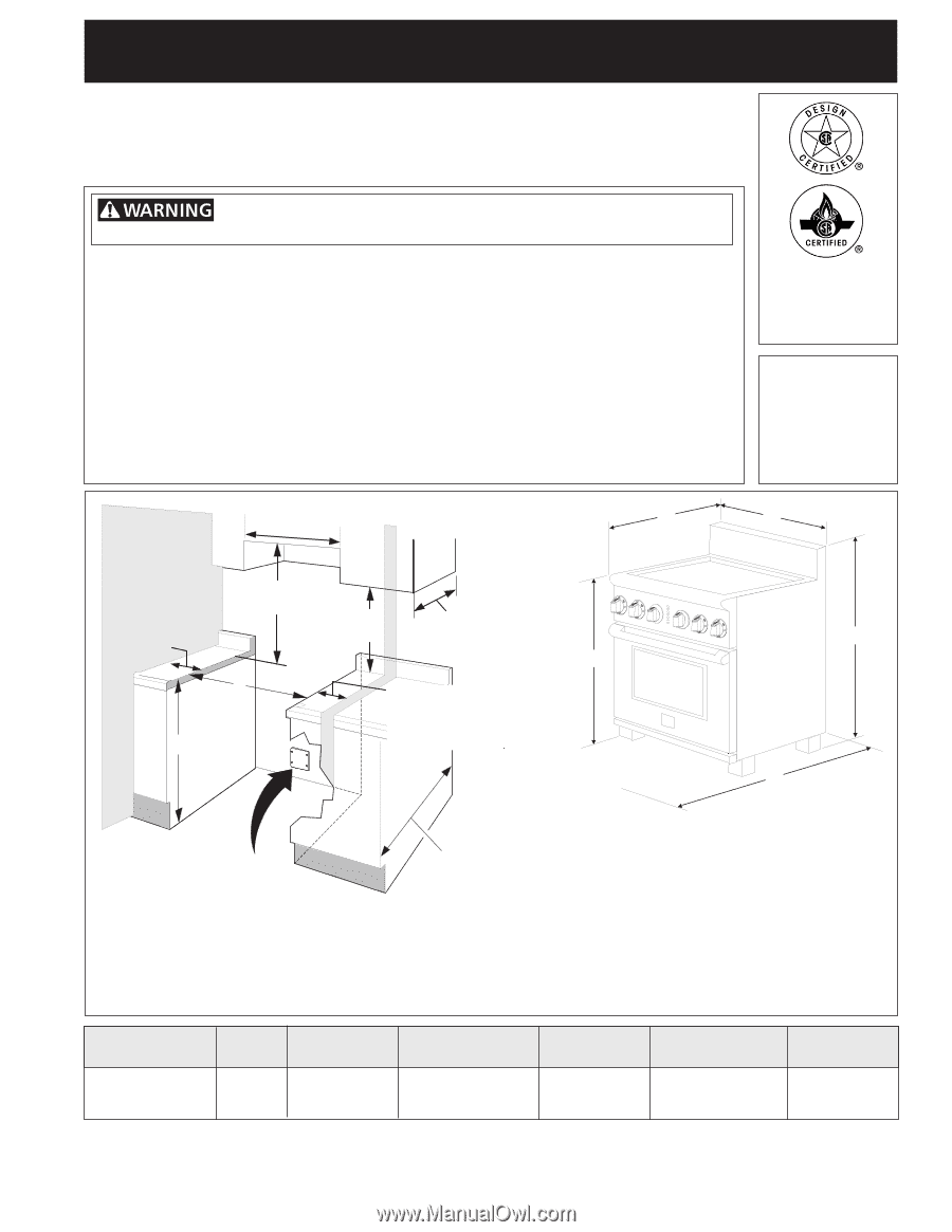
30" & 36" DUAL FUEL RANGE INSTALLATION INSTRUCTIONS
(Model with Electric Oven and Gas Cooktop)
If the information in this manual is not followed exactly, a fire
or explosion may result causing property damage, personal injury or death.
FOR YOUR SAFETY:
— Do not store or use gasoline or other flammable vapors and liquids in
the vicinity of this or any other appliance.
— WHAT TO DO IF YOU SMELL GAS:
•
Do not try to light any appliance.
•
Do not touch any electrical switch; do not use any phone in your building.
•
Immediately call your gas supplier from a neighbor's phone. Follow the
gas supplier's instructions.
•
If you cannot reach your gas supplier, call the fire department.
— Installation and service must be performed by a qualified installer, service
agency or the gas supplier.
P/N 318201773 (0809) Rev. B
English - pages 1-12; Español - páginas 13-24
Français - pages 25-36
; Wiring Diagram - page 36
Note: Wiring diagram for this model is enclosed in this booklet (see page 36).
Printed in United States
INSTALLATION AND SERVICE MUST BE PERFORMED BY A QUALIFIED INSTALLER.
IMPORTANT: SAVE FOR LOCAL ELECTRICAL INSPECTOR'S USE.
READ AND SAVE THESE INSTRUCTIONS FOR FUTURE REFERENCE.
OBSERVE ALL GOVERNING CODES AND ORDINANCES.
B.
WIDTH
29 7/8"
( 75.9 cm)
C.
DEPTH TO FRONT
OF RANGE
27 1/2"
(69.9 cm)
E.
DEPTH WITH
DOOR OPEN
45 1/2"
(115.6 cm)
F.
HEIGHT OF
COUNTERTOP
36" (91.4 cm) Standard
35 3/4" (90.8 cm) Min.
G.
MINIMUM
CUTOUT WIDTH
30 1/16"
(76.4 cm)
NOTE:
24" (61 cm) minimum clearance between the
cooktop and the bottom of the cabinet when the bottom
of wood or metal cabinet is protected by not less than
1/4" (0.64 cm) flame retardant millboard covered with
not less than No. 28 MSG sheet metal, 0.015" (0.4 mm)
stainless steel, 0.024" (0.6 mm) aluminum, or 0.020"
(0.5 mm) copper.
30" (76.2 cm) minimum clearance when the cabinet is
unprotected.
Do not pinch the power supply cord between the range
and the wall.
Do not seal the range to the side cabinets.
13" Max.
(33 cm Max.)
24" Min.
(61 cm Min.)
24 1/2" Max.
(62.2 cm Max.)
29 7/8" Min.
(75.9 cm Min.)
See
note
Grounded
Wall Outlet or
junction box
location
WALL
WALL
If there is a wall:
7" Min.
(17.78 cm Min cm Min.)
Left side
18" Min.
(45.7 cm Min.)
F
G
If there is a wall:
7" Min.
(17.78 cm Min.)
Right side
A
B
C
D
E
Figure 1 - 30" Range (36" Range, see next page)
Note:
For
appliances
installed in
the state of
Massachusetts
see page 3.
Refer to your
serial plate for
applicable agency
certification
A.
HEIGHT
41 5/8" (105.7 cm) Min.
42 5/8" (108.3 cm) Max.
D.
HEIGHT OF COOKTOP
35 3/4" (90.8 cm) Min.
36 3/4" (93.3 cm) Max.