Electrolux E30DF74GPS Installation Instructions - Page 7
Four Conductor Wire Connection, to the Junction Box, Range Placement
 |
View all Electrolux E30DF74GPS manuals
Add to My Manuals
Save this manual to your list of manuals |
Page 7 highlights
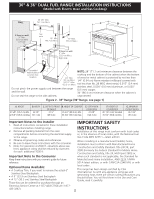
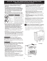
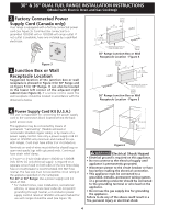
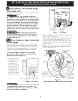
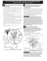
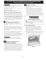
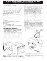
30" & 36" DUAL FUEL RANGE INSTALLATION INSTRUCTIONS (Model with Electric Oven and Gas Cooktop) 6.B Four Conductor Wire Connection to the Junction Box If oven is used in a new branch circuit installation (1996 NEC), mobile home, recreational vehicle, or where local codes do not permit connecting the appliance cable ground wire to the power supply cable neutral (white) wire you must use a 4 wire power supply cable (see figure 12): 1. Disconnect the power supply. 2. In the circuit breaker, fuse box or junction box: Connect appliance and power supply cable wires as shown in figure 12. Ground Wire Red Wires Cable from Power Supply White Wire Ground Wire (Bare or Green Wire) Black Wires White Wire Junction Box U.L.-Listed Conduit Connector (or CSA listed) Cable from appliance Figure 12 4-WIRE GROUNDED JUNCTION BOX DO NOT ground to a gas supply pipe. DO NOT connect to electrical power supply until appliance is permanently grounded. Connect the ground wire before turning on the power (Figure 12). 7. Range Placement To eliminate the risk of burns or fire from reaching over heated surface units, cabinet storage space located above the range should be avoided. If cabinet storage space is to be provided, the risk can be reduced by installing a range hood that projects horizontally a minimum of 5" (12.7 cm) beyond the bottom of the cabinet. Center Line of Range Follow instructions for the type of installation you have Figure 13 If range will be installed with a cabinet on both sides, draw a center line on the floor between the cabinets (see figure 13). If back of range will not be flush with the wall (the location of the outlet may not allow the range to be positioned against the wall), draw a line on the floor where the back edge of the range will be. Now install anti-tip bracket (see "Anti-Tip Bracket Installation", page 12). If range will be installed with a cabinet on one side only, move the range into final position. Draw a line on the floor along the side of the range that is not against the cabinet. If back of range will not be flush with the wall (the location of the outlet may not allow the range to be positioned against the wall), draw a line on the floor where the back edge of the range will be. Now install anti-tip bracket (see "Anti-Tip Bracket Installation", page 12). If range will not be installed against a cabinet, move range into final position. Draw a line on the floor along both sides of the range. If back of range will not be flush with the wall (the location of the outlet may not allow the range to be positioned against the wall), draw a line on the floor where the back edge of the range will be. Now install anti-tip bracket (see "Anti-Tip Bracket Installation", page 12). 7
-
 1
1 -
 2
2 -
 3
3 -
 4
4 -
 5
5 -
 6
6 -
 7
7 -
 8
8 -
 9
9 -
 10
10 -
 11
11 -
 12
12 -
13
-
14
-
15
-
16
-
17
-
18
-
19
-
20
-
21
-
22
-
23
-
24
-
25
-
26
-
27
-
28
-
29
-
30
-
31
-
32
-
33
-
34
-
35
-
36
 |
 |
