Electrolux EFLW427UIW Wiring Diagram English
Electrolux EFLW427UIW Manual
 |
View all Electrolux EFLW427UIW manuals
Add to My Manuals
Save this manual to your list of manuals |
Electrolux EFLW427UIW manual content summary:
- Electrolux EFLW427UIW | Wiring Diagram English - Page 1
is intended for Qualified Technicians Only. TABLE OF CONTENTS Washer Tech Data Sheet 1 Diagnostic Mode Tests 2 Demo Mode/Washer Error Codes 3 Washer Error Codes 4 Troubleshooting Tests 5 Wiring Diagrams 19 Safety items throughout this manual are labeled with a WARNING or CAUTION based on the - Electrolux EFLW427UIW | Wiring Diagram English - Page 2
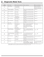
no test for 400 series) Wash compartment Bleach compartment Softener compartment Stain compartment Wash compartment Door unlock • LED indicators • Motor • Heater • NTC • Door lock • Drum light Motor moves after machine fills with 60 mm of water. Heater heats until temperature reaches 70º C. Max. - Electrolux EFLW427UIW | Wiring Diagram English - Page 3
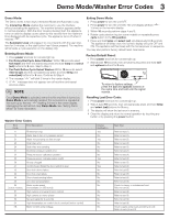
machine will simulate a cycle execution on the display only. Entering Demo Mode: 1 Press power and look for console light up. 2 For Rotary Dial Cycle Select Washer: Within 10 seconds select fast wash to test (4) 32 Pressure sensor calibration problem No Refer to test (4) 35 Pressure sensor - Electrolux EFLW427UIW | Wiring Diagram English - Page 4
4 Washer Error Codes Washer Error Codes, continued Error Code 5C 5D 5E 5F 62 66 ( wash pump triac alarm User interface protocol incongruence error User interface mother board protocol incongruence Console or main board control problem (incompatible machine configuration) Main board control problem - Electrolux EFLW427UIW | Wiring Diagram English - Page 5
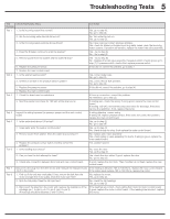
Troubleshooting Tests 5 Test Check/Test Activity Steps Number Correction Test 1 1. Is the Check the drain hose for restrictions. If there is a restriction, correct the problem. No restriction, go to step (2). 2. Start the washer and check for 120 VAC at the drain pump. If reading zero, check - Electrolux EFLW427UIW | Wiring Diagram English - Page 6
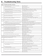
6 Troubleshooting Tests Washer Troubleshooting Tests, continued Test 9 Test 10 Test 11 Test control board. Check wiring to concentrated wash pump If wiring is bad, correct wiring problem. If wiring is good, replace concentrated wash pump. If the problem is not corrected, replace the main control - Electrolux EFLW427UIW | Wiring Diagram English - Page 7
câblage 19 Les mesures de sécurité présentées dans ce guide sont identifiées par les mots AVERTISSEMENT ou ATTENTION selon le type ) Pour le mode diagnostic : 1 Appuyer sur power pour mettre la machine sous tension. 2 Tourner le bouton sélecteur de cycle (certains mod com Canada 1-800-265-8352 - Electrolux EFLW427UIW | Wiring Diagram English - Page 8
et moteur • Capteur de pression • Valve d'eau froide • Moteur • Chauffe-eau • CTN • Verrou de porte • Éclairage du tambour Le moteur tourne une fois que la machine est remplie de 60 mm d'eau. Le chauffe-eau chauffe l'eau jusqu'à ce que la température atteigne 70º C. La durée maximale du test est - Electrolux EFLW427UIW | Wiring Diagram English - Page 9
avec sélecteur à bouton : Dans un délai de 10 secondes sélectionner fast wash et puis tenir enfoncées ensemble temp et select (set) pendant 3 secondes. se fasse entendre. Une fois Mode Démo activé, chaque fois que la machine est mise sous tension, Mode Démo est automatiquement repris, ce qui - Electrolux EFLW427UIW | Wiring Diagram English - Page 10
protocole de la carte mère de l'interface utilisateur Oui 93 Problème de console ou de commande du panneau principal Oui (configuration de machines incompatibles) 94 Problème de commande du panneau principal Oui (configuration de cycles incompatibles) 97 Problème de console ou de commande - Electrolux EFLW427UIW | Wiring Diagram English - Page 11
Tests de dépistage 11 Test Étapes de test/vérification Numéro Test 1 1. Est-ce que le flux d'entrée de l'eau est normal ? 2. Est-ce que les robinets d'arrivée de l'eau sont ouverts ? 3. Est-ce que la pression d'arrivée d'eau est supérieure à 20 psi ? 4. Est-ce que l'eau de remplissage continue à - Electrolux EFLW427UIW | Wiring Diagram English - Page 12
12 Tests de dépistage Tests de dépistage, suite Test 9 1. Démonter la courroie du moteur et faire tourner la poulie du moteur. Non. Remplacer le moteur. Le moteur tourne-t-il librement ? Oui. Passer à l'étape 2. 2. Faire tourner la poulie de la cuve. La cuve tourne-t-elle librement ? Non. Vé - Electrolux EFLW427UIW | Wiring Diagram English - Page 13
o daños materiales. Este símbolo le alerta de situaciones PRECAUCIÓN que podrían provocar lesiones o daños materiales. La información contenida en este manual está destinada exclusivamente a técnicos de mantenimiento cualificados. • NO meta la mano en el aparato si el tambor o la cuba están girando - Electrolux EFLW427UIW | Wiring Diagram English - Page 14
14 Pruebas del modo Diagnóstico MODO NÚMERO (solo determinados modelos) NOMBRE DE LA PRUEBA COMPONENTES SOMETIDOS A PRUEBA CONDICIONES DE LA PRUEBA INFORMACIÓN VISUALIZADA Luces, Botones • Indicadores LED • Pantalla LED • Respuesta de botones Número de tecla pulsada. Nota: este número es - Electrolux EFLW427UIW | Wiring Diagram English - Page 15
Pulse el botón power y espere a que se ilumine la consola. 2 Para Lavadora con selector giratorio de ciclo: En 10 segundos seleccione fast wash y después, mantenga pulsados simultáneamente los botones temp y select durante 3 segundos. Vaya al paso 4. 3 Para Lavadora con pulsadores de selección de - Electrolux EFLW427UIW | Wiring Diagram English - Page 16
16 Códigos de error Códigos de error de la lavadora (continuación) Código de error 5B Descripción del error Baja tensión del control del motor Pantalla Notificación No 5C 5D 5E 5F 62 66 (en determinados modelos) 68 (en determinados modelos) 69 (en determinados modelos) 6A (en determinados - Electrolux EFLW427UIW | Wiring Diagram English - Page 17
Pruebas de resolución de problemas 17 Prueba Número Prueba 1 Prueba 2 Prueba 3 Prueba 4 Prueba 5 Prueba 6 Prueba 7 Prueba 8 Comprobaciones/pruebas de actividad Solución 1. ¿El flujo de agua de entrada es normal? 2. ¿Están abiertas las llaves de agua entrante? 3. ¿La presión de agua de entrada es - Electrolux EFLW427UIW | Wiring Diagram English - Page 18
18 Pruebas de resolución de problemas Pruebas de resolución de problemas (continuación) Prueba 9 1. Quite la correa del motor y gire la polea del motor. ¿El motor gira libremente? 2. Gire la polea de la cuba. ¿La cuba gira libremente? 3. Desconecte la clavija del motor de accionamiento y mida la - Electrolux EFLW427UIW | Wiring Diagram English - Page 19
Wiring Diagrams 19 Wiring Diagram - 427 Series Washer (A10860902) Schéma de câblage - Laveuse de série 427 | Esquema de cableado - Lavadora Serie 427 CAUTION ELECTRICAL SHOCK HAZARD To avoid electrical shock, disconnect electrical current before servicing. ATTENTION RISQUE DE CHOC ÉLECTRIQUE Pour - Electrolux EFLW427UIW | Wiring Diagram English - Page 20
20 Wiring Diagrams Wiring Diagram - 527 Series Washer (A10861002) Schéma de câblage - Laveuse de série 527 | Esquema de cableado - Lavadora Serie 527 CAUTION ELECTRICAL SHOCK HAZARD To avoid electrical shock, disconnect electrical current before servicing. ATTENTION RISQUE DE CHOC ÉLECTRIQUE Pour - Electrolux EFLW427UIW | Wiring Diagram English - Page 21
Wiring Diagrams 21 Wiring Diagram - 627 Series Washer (A10860602) Schéma de câblage - Laveuse de série 627 | Esquema de cableado - Lavadora Serie 627 CAUTION ELECTRICAL SHOCK HAZARD To avoid electrical shock, disconnect electrical current before servicing. ATTENTION RISQUE DE CHOC ÉLECTRIQUE Pour - Electrolux EFLW427UIW | Wiring Diagram English - Page 22
22 Notes | Remarques | Notas - Electrolux EFLW427UIW | Wiring Diagram English - Page 23
Notes | Remarques | Notas 23 - Electrolux EFLW427UIW | Wiring Diagram English - Page 24
24 Notes | Remarques | Notas
-
 1
1 -
 2
2 -
 3
3 -
 4
4 -
 5
5 -
 6
6 -
 7
7 -
8
-
9
-
10
-
11
-
12
-
13
-
14
-
15
-
16
-
17
-
18
-
19
-
20
-
21
-
22
-
23
-
24
 |
 |

1
A11200303 (1902)
USA 1-877-435-3287
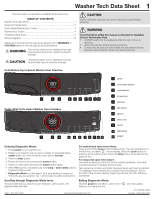
This information is intended for Qualified Technicians Only.
TABLE OF CONTENTS
Entering Diagnostic Mode:
1 Press
power
to turn machine on.
2 Rotate cycle selector ring (on some models) or repeatedly press
cycles
button (on other models) to set cycle to
normal
.
3 Press the
start
button.
4 Power off machine by pressing the
power
button.
5 Power on machine by pressing the
power
button again.
6 Within
10
seconds, simultaneously hold
temp
+
select (set)
buttons
together for
3
seconds.
7
Diagnostic Mode
is active when LED’s start blinking in sequence.
This is the pre-test position “
”, which tests the lights and buttons.
Safety items throughout this manual are labeled with a
WARNING
or
CAUTION
based on the risk type as described below:
Washer Tech Data Sheet
www.electroluxappliances.com
Canada 1-800-265-8352
Push Button Cycle Select Washer User Interface
Rotary Dial Cycle Select Washer User Interface
This symbol alerts you to situations that may
cause bodily injury or property damage.
This symbol alerts you to situations that may
cause serious body harm, death or property
damage.
CAUTION
WARNING
CAUTION
Unless otherwise directed, disconnect electrical current before
servicing.
Washer Tech Data Sheet
.......................................................................
1
Diagnostic Mode Tests
..........................................................................
2
Demo Mode/Washer Error Codes
..........................................................
3
Washer Error Codes
..............................................................................
4
Troubleshooting Tests
............................................................................
5
Wiring Diagrams
..................................................................................
19
cancel
start/pause
10
7
1
power
2
cycle status display
3
cycle selector
4
temperature
5
soil level
6
spin speed
7
options
8
select (set)
9
2
1
6
3
8
5
4
9
10
2
7
1
6
3
8
5
4
9
10
11
PODS
®
11
WARNING
The information within this manual is intended for Qualified
Service Technicians Only.
•
DO NOT reach into the appliance while the tub or drum is
spinning.
•
Disconnect power before servicing machine.
•
Certain internal parts are intentionally not grounded and may
present a risk of electric shock only during servicing.
Scrolling through Diagnostic Mode tests:
Tests are selected by using the same method to select cycles.
See
Diagnostic Mode Tests Table.
For push button cycle select dryer:
Press and hold the
cycle
button for
2
seconds. The unit will advance to
the first test; and flash “
”
on the display. Press the
cycle
button to
advance to the following test. Press the
temp
button to go back to the
previous test.
For rotary dial cycle select dryer:
Use knob to advance to the first test by rotating clockwise. Turn knob
counterclockwise to navigate previous tests.
Test sequence numbers are briefly displayed when each test is selected.
The displayed test numbers also correspond to the selector LEDs to
the right of the numeric display; beginning with the top LED, following
downward.
Exiting Diagnostic Mode:
Hold the
power
key for
3
sec, when not in “
” test step Lights/
Buttons, or unplug the unit.