Electrolux EWFLS70JSS Wiring Diagram (All Languages)
Electrolux EWFLS70JSS Manual
 |
UPC - 012505382819
View all Electrolux EWFLS70JSS manuals
Add to My Manuals
Save this manual to your list of manuals |
Electrolux EWFLS70JSS manual content summary:
- Electrolux EWFLS70JSS | Wiring Diagram (All Languages) - Page 1
(board located inside the front control panel) DL - Door Lock READING ERROR CODES 1. Wake the washer up by pressing any experienced. Troubleshoot the problem by using charts on the pages 3-5. If there is no error displayed and the washer momentarily models and all lights on for the 1¼"x4¾" display - Electrolux EWFLS70JSS | Wiring Diagram (All Languages) - Page 2
lock solenoid will deactivate and the loading door can be opened. When SERVICE", "NO WATER" or "CHECK HOSES". Correct the action and repeat the cycle for proper installation. Washer will exit the "INSTAL CYCLE" and return to normal operation the next time the knob is turned. 1¼"x4¾" Display Models - Electrolux EWFLS70JSS | Wiring Diagram (All Languages) - Page 3
. Main Board control problem. Console or Main Board control problem. Console control problem. Communication problem between microprocessor and external EEPROM. Communication protocol Power supply frequency out of limits Power supply voltage too high Power supply voltage too low Main Voltage sensing - Electrolux EWFLS70JSS | Wiring Diagram (All Languages) - Page 4
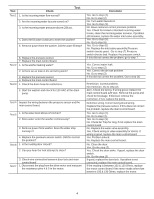
Is the water level above 4.5 inches? 2. Does water enter the washer continuously? 3. Remove power from washer. Does the water stop coming in? 4. Replace the pressure sensor switch. Did this correct the problem? Test 6 1. Is the loading door closed? 2. Can you hear the lock attempt to close? Test - Electrolux EWFLS70JSS | Wiring Diagram (All Languages) - Page 5
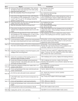
board.If the readings are incorrect, replace the motor. Test 9: 1. Remove the belt from the motor and spin the motor pulley. Does the motor spin free? 2. . If the readings are incorrect, replace the heating element.If the problem is not corrected, replace the main control board. No, replace the - Electrolux EWFLS70JSS | Wiring Diagram (All Languages) - Page 6
momentanément et s'arrête de nouveau : 1. Écoutez si un relais de la commande se ferme peu de temps après avoir appuyé sur la touche "Start (Départ)/Pause". 2. Vérifiez si les connexions de la MB sont ajustées fermement. Pour effacer le dernier code d'erreur en mémoire : • Appuyez sur le bouton - Electrolux EWFLS70JSS | Wiring Diagram (All Languages) - Page 7
) positions à partir de la position de départ. La dernière version du logiciel sera pr INSTAL PASS! » (Installation réussie) ou vous demandera d'effectuer une action en indiquant les messages CALL SERVICE (Demander du service installation. Appuyez sur la touche de réglage, puis suivez les instructions - Electrolux EWFLS70JSS | Wiring Diagram (All Languages) - Page 8
à zéro de la commande Conseiller au client de réduire la quantité de savon utilisée. Se référer au test (16) Se référer au test (18). EF8 Touche bloquée Vérifier toutes les - Electrolux EWFLS70JSS | Wiring Diagram (All Languages) - Page 9
Test Test 1 Test Vérification Correction 1.Est-ce que le flux d'entrée de l'eau est normal ? Oui. Passez à l'étape (4). 2.Est-ce que les robinets d'arrivée de l'eau sont ouverts? 3.Est-ce que la pression d'arrivée d'eau est supérieure à 20 psi ? Non. Passez à l'étape (2) Non. Ouvrez les - Electrolux EWFLS70JSS | Wiring Diagram (All Languages) - Page 10
Test Test Vérification Correction Test 7 1.Débranchez le raccord du moteur et mesurez la Si la valeur lue se situe entre 105 et 130 Ohms, remplacez résistance des broches 4 et 5 du moteur. la carte de contrôle de moteur.Si le compteur indique d'autres valeurs que 105 et 130 Ohms, remplacez - Electrolux EWFLS70JSS | Wiring Diagram (All Languages) - Page 11
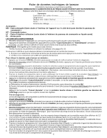
Hoja técnica de lavadora Esta información está destinada exclusivamente a los técnicos calificados. PRECAUCIÓN: DESCONECTE LA CORRIENTE ELÉCTRICA ANTES DE DAR MANTENIMIENTO O SERVICIO Por favor devuelva esta hoja a su sobre en el producto para referencia futura Contenido Página Explicación de los - Electrolux EWFLS70JSS | Wiring Diagram (All Languages) - Page 12
partes del programa que quiso restablecer se encontrarán con los valores de fábrica. Ciclo de instalación Antes de ingresar al Ciclo de Instalación (Install se mostrará "INSTAL PASS!" (INSTAL. APROBADA); de lo contrario, durante el ciclo se indicará alguna acción, como "CALL SERVICE" (llame al - Electrolux EWFLS70JSS | Wiring Diagram (All Languages) - Page 13
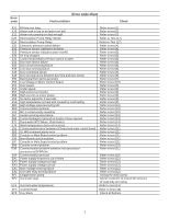
Código de error Tabla de códigos de error Condición de falla Revise E11 Demasiado tiempo para el llenado. E13 Fuga de agua en la tina o fuga de aire en la campana de aire. E21 El drenado de agua no es lo suficientemente rápido. E25 Sensor de relé de bomba de recirculación E26 Relé de bomba de - Electrolux EWFLS70JSS | Wiring Diagram (All Languages) - Page 14
Prueba Prueba 1 Prueba 2 Prueba 3 Prueba 4 Prueba 5 Prueba 6 Prueba 7 Prueba 8 Prueba Revise Corrección 1.¿El flujo del agua entrante es normal? 2.¿Están abiertas las llaves de agua? 3.La presión del agua entrante está sobre (20) psi. 4.¿El agua para llenado continúa entrando a la lavadora? 5. - Electrolux EWFLS70JSS | Wiring Diagram (All Languages) - Page 15
Prueba Revise Prueba Corrección Prueba 9 3.Desconecte la clavija del motor y mida la resistencia de los pines (pin 1 a pin 2, pin 1 a pin 3, pin 2 a pin 3). Todas las lecturas deben estar entre 3 y 6 Ohms. 1.Quite la banda del motor y gire la polea del motor. ¿El motor gira libremente? 2.Gire - Electrolux EWFLS70JSS | Wiring Diagram (All Languages) - Page 16
-
 1
1 -
 2
2 -
 3
3 -
 4
4 -
 5
5 -
 6
6 -
 7
7 -
8
-
9
-
10
-
11
-
12
-
13
-
14
-
15
-
16
 |
 |

137316000A
(1004)
Washer Tech Data Sheet
This information is intended for Qualified Technicians Only.
CAUTION: DISCONNECT ELECTRICAL CURRENT BEFORE SERVICING
Please Return This Sheet to its Envelope in the Product for Future Reference
Contents
Page
Error code explanation
.............................................
1
Diagnostics
........................................................
1-2
Error Code Chart
.....................................................
3
Tests
..................................................................
4-5
Français…………………………………………
.........
6-10
Español…………………………………………
........
11-15
Wiring Diagram……………………………………
........
16
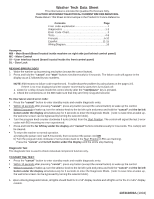
Acronyms:
MB – Main Board (Board located inside machine on right side just behind control panel.)
MC – Motor Control
UI – User interface board (board located inside the front control panel)
DL – Door Lock
READING ERROR CODES
1.
Wake the washer up by pressing any button (except the cancel button).
2.
Press and hold the
“cancel
”
and
“start”
buttons simultaneously for 6 seconds. The failure code will appear in the
display as an E followed by two numbers.
NOTE:
E00 means no failure code experienced.
Troubleshoot the problem by using charts on the pages 3-5.
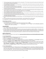
If there is no error displayed and the washer momentarily starts then turns back off:
1.
Listen for a relay closure inside the control shortly after the
“start/pause”
key is pressed.
2.
Check the connections on the MB make sure that they are firmly snug and secured.
To clear latest stored error code:
•
Press the
“cancel”
button to enter standby mode and enable diagnostic entry.
•
Within 10 seconds after pressing
“cancel”
, press any button (except the cancel button) to wake up the control.
•
Within 5 seconds of wake up, turn the selector knob to the far left cycle and press and hold the
“cancel”
and
the far left
button under the display
simultaneously for 3 seconds to enter the Diagnostic Mode.
(note: to save time at wake up,
the welcome screen can be bypassed by turning the selector knob).
•
Turn the program knob counter clockwise 9 turns (clicks) from the
S
t
art Position. The control will signal the last 5 error
codes with E00 meaning no error experienced.
•
Press and hold the
far left key under the display
and
“cancel”
buttons simultaneously for 3 seconds. The code(s) will
be cleared.
•
To return the washer to normal operation.
a) Unplug the power cord, wait 5-8 seconds, then reconnect the power cord
OR
b) Turn the program knob clockwise 2 turns (clicks) back to the
S
t
art Position (LEDs are flashing).
Press the
“cancel
” and
far left button under the display
until the LEDs stop flashing.
Diagnostic Test
The diagnostic test is used to check individual component function only.
T
O ST
ART THE TEST
:
•
Press the
“cancel”
button to enter standby mode and enable diagnostic entry.
•
Within 10 seconds after pressing
“cancel”
, press any button (except the cancel button) to wake up the control.
•
Within 5 seconds of wake up, turn the selector knob to the far left cycle and press and hold the
“cancel”
and
the far left
button under the display
simultaneously for 3 seconds to enter the Diagnostic Mode.
(note: to save time at wake up,
the welcome screen can be bypassed by turning the selector knob).
1.
Upon entering Diagnostic Mode, all lights should flash for 1¼”x2” display models and all lights on for the 1¼”x4¾” display
models.