Epson BrightLink 710Ui Installation Guide - Ultra-Short Throw Wall Mount ELPMB
Epson BrightLink 710Ui Manual
 |
View all Epson BrightLink 710Ui manuals
Add to My Manuals
Save this manual to your list of manuals |
Epson BrightLink 710Ui manual content summary:
- Epson BrightLink 710Ui | Installation Guide - Ultra-Short Throw Wall Mount ELPMB - Page 1
Installation Guide Guide d'installation - Epson BrightLink 710Ui | Installation Guide - Ultra-Short Throw Wall Mount ELPMB - Page 2
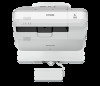
About This Installation Guide This guide describes how to mount the ultra-short-throw projectors listed below to a wall using the Epson® ELPMB53 wall mount. The following projectors are covered by this guide: • BrightLink® 710Ui • BrightLink Pro 1470Ui • PowerLite® 700U Safety Instructions For - Epson BrightLink 710Ui | Installation Guide - Ultra-Short Throw Wall Mount ELPMB - Page 3
at least two qualified service personnel. If you need to loosen any screws during installation, be careful not to drop the wall mount. If the wall mount or projector falls, it could cause personal injury or property damage. Install the wall mount so that it can sufficiently support the weight of the - Epson BrightLink 710Ui | Installation Guide - Ultra-Short Throw Wall Mount ELPMB - Page 4
may overheat and the power may turn off without warning. • The projector must be installed in one of the following locations in order for the Touch Unit to function properly (if applicable): • Mounted on a wall or suspended from the ceiling with images projected from in front of the screen - Epson BrightLink 710Ui | Installation Guide - Ultra-Short Throw Wall Mount ELPMB - Page 5
English 1 Package Contents 7 2 Specifications 8 3 Connecting Devices 11 4 Positioning the Projector 13 Installation worksheet for projecting on a pre-installed wall-mounted board 14 Installation worksheet for projecting on a plain wall 15 Projection distance worksheets 16 Diagonal - Epson BrightLink 710Ui | Installation Guide - Ultra-Short Throw Wall Mount ELPMB - Page 6
40 Attach the wall plate cover and end cap 40 Attach the cable cover to the projector 41 8 Appendix 42 Installing the Touch Unit and Control Pad 42 Using the Easy Interactive Function 42 Correcting the Image Shape on a Curved Screen 42 Attaching a Security Cable 43 Limited Warranty - Epson BrightLink 710Ui | Installation Guide - Ultra-Short Throw Wall Mount ELPMB - Page 7
/projector installation M6 × 20 mm hexagon shoulder head bolt with washer/spring washer 1 For wall mount/wall plate installation M6 × 20 mm cross recessed head shoulder screw 3 with plastic washer • Use the bolts or screws supplied with the wall mount to install it as directed in this guide - Epson BrightLink 710Ui | Installation Guide - Ultra-Short Throw Wall Mount ELPMB - Page 8
2 Specifications Item Specification Wall mount weight (including the Approx. 17.4 lb - 3-axis adjustment Refer to the illustration on page 9 s p. 36 s p. 36 s p. 37 Wall plate cover When installing the wall plate cover, you need a space of approximately 10.3 inches (263 mm) from the center of - Epson BrightLink 710Ui | Installation Guide - Ultra-Short Throw Wall Mount ELPMB - Page 9
wall plate is in three pieces when shipped. Use the included M4 × 12 mm bolts (×5) to attach the separate pieces together before mounting the projector. See page 23 for instructions. 5.2 in. (131 mm) 3.9 in. (99 mm) 0.9 in. (24 mm) 3.9 in. (99 mm) 0.9 in. (24 mm) 1.8 in. 1.8 in. (45 mm) (45 mm - Epson BrightLink 710Ui | Installation Guide - Ultra-Short Throw Wall Mount ELPMB - Page 10
unit to the front or back, you can adjust the installation position of the projector. When the screen size is less than 85 inches, install it at the position marked with a stamp on the mount arm. When the screen size is 85 inches or more, install it at the position marked with a arm. stamp on - Epson BrightLink 710Ui | Installation Guide - Ultra-Short Throw Wall Mount ELPMB - Page 11
where the wall mount is to be installed. Make sure you Guide for your projector Epson DC-07) USB cable (for Easy Interactive Function) Dedicated USB cable (supplied with document camera) For Interactive Use When interacting with a computer, you need a USB cable. However, when using the projector - Epson BrightLink 710Ui | Installation Guide - Ultra-Short Throw Wall Mount ELPMB - Page 12
with the BrightLink Pro 1470Ui. It provides a convenient alternative to the remote control for turning on the projector and selecting whiteboard mode. You must install the projector before installing the control pad. See the documentation included with your projector for details on mounting and - Epson BrightLink 710Ui | Installation Guide - Ultra-Short Throw Wall Mount ELPMB - Page 13
guide covers your projector's native resolution and aspect ratio. For other resolutions and aspect ratios, use the Throw Distance Calculator at www.epson.com/support (U.S.), www.epson.ca/support (Canada), or www.epson.com/jm/support (Latin America). You can project onto a pre-installed whiteboard - Epson BrightLink 710Ui | Installation Guide - Ultra-Short Throw Wall Mount ELPMB - Page 14
surface, you must install the Touch Unit on the whiteboard or screen. See the documentation included with your projector for details on mounting the Touch Unit. Distance Calculator at www.epson.com/support (U.S.), www.epson.ca/support (Canada), or www.epson.com.jm (Latin America) to determine - Epson BrightLink 710Ui | Installation Guide - Ultra-Short Throw Wall Mount ELPMB - Page 15
with the center of the image area. Follow the instructions on page 23 to install the projector. Installation worksheet for projecting on a plain wall 10 in. Distance Calculator at www.epson.com/support (U.S.), www.epson.ca/support (Canada), or www.epson.com.jm (Latin America) to determine - Epson BrightLink 710Ui | Installation Guide - Ultra-Short Throw Wall Mount ELPMB - Page 16
center line on the template sheet with the center of the image area. Follow the instructions on page 23 to install the projector. Projection distance worksheets The tables on the following pages provide installation information for the native image size. The minimum ceiling height is based on an - Epson BrightLink 710Ui | Installation Guide - Ultra-Short Throw Wall Mount ELPMB - Page 17
7.5 in. (192.3 mm) English Diagonal image size and mounting position 2.4 to 17 in. (62 to 432 mm) 1.06 in. (27 mm) Wall plate arm extension. When the diagonal image size is 85 inches or more, mount the 3-axis adjustment unit at the position marked with a stamp. When the diagonal image size is - Epson BrightLink 710Ui | Installation Guide - Ultra-Short Throw Wall Mount ELPMB - Page 18
the wall plate. Base position Stamp on plate Notch on mount arm Installation measurement tables Use the following installation measurement tables for your projector. The measurements may differ depending on the location where you place the projector. When projecting in Tele mode, the quality of the - Epson BrightLink 710Ui | Installation Guide - Ultra-Short Throw Wall Mount ELPMB - Page 19
English Measurements in Inches for WUXGA Projectors in Native Resolution Diagonal Min. ceiling image size (S) height** Image width (w) Image height (h) Distance from top of image to Min. projection Sliderscale bottom wall plate - Epson BrightLink 710Ui | Installation Guide - Ultra-Short Throw Wall Mount ELPMB - Page 20
Diagonal Min. ceiling image size (S) height** Image width (w) Image height (h) Distance from top of image to Min. projection Sliderscale bottom wall plate distance (a) mark (b) holes (c) Distance from top of image to temporary wall plate hole (d) 114"* 144.6 96.7 60.4 13.0 13.9 14.2 - Epson BrightLink 710Ui | Installation Guide - Ultra-Short Throw Wall Mount ELPMB - Page 21
English Measurements in Centimeters for WUXGA Projectors in Native Resolution Diagonal Min. ceiling image size (S) height** Image width (w) Image height (h) Distance from top of image to Min. projection Sliderscale bottom wall plate - Epson BrightLink 710Ui | Installation Guide - Ultra-Short Throw Wall Mount ELPMB - Page 22
Diagonal Min. ceiling image size (S) height** Image width (w) Image height (h) Distance from top of image to Min. projection Sliderscale bottom wall plate distance (a) mark (b) holes (c) Distance from top of image to temporary wall plate hole (d) 114"* 291.2 245.5 153.5 33.2 35.4 36.1 - Epson BrightLink 710Ui | Installation Guide - Ultra-Short Throw Wall Mount ELPMB - Page 23
is about 44 lb (20 kg). ❏ Do not hang cables over the wall mount. ❏ Install the wall mount so that it can sufficiently support the weight of the projector and wall mount, and resist any horizontal vibration. Use M10 nuts and bolts and make sure to use appropriate wall anchors for your wall type - Epson BrightLink 710Ui | Installation Guide - Ultra-Short Throw Wall Mount ELPMB - Page 24
the alignment ( ). Then, tighten the M4 × 12 mm hexagon socket head cap bolt. 3. Attach the 3-axis adjustment unit and slide plate to the projector. Attach the 3-axis adjustment unit and slide plate to the projector using the M4 × 12 mm hexagon socket head cap bolts (×4) supplied. Bolt locations 24 - Epson BrightLink 710Ui | Installation Guide - Ultra-Short Throw Wall Mount ELPMB - Page 25
English B Install the wall plate on the wall 1. Determine the template sheet position. line of template sheet line of template sheet Center line of projection surface If you want to hide the projector power plug under the wall plate cover, make sure the power outlet is located in the empty space to - Epson BrightLink 710Ui | Installation Guide - Ultra-Short Throw Wall Mount ELPMB - Page 26
4. Determine the position of the wall plate's mounting holes. Use at least four mounting holes. Steps 5 to 9 below provide instructions for attaching the wall plate to a concrete wall. 5. Drill holes of the following diameters and depths. Drill diameter Pilot hole depth Anchor hole depth 0.41 - Epson BrightLink 710Ui | Installation Guide - Ultra-Short Throw Wall Mount ELPMB - Page 27
number for the slider measure (b). 2. Loosen the M4 × 12 mm hexagon socket head cap bolts (×2), and then pull out the slider on the wall mount. Align the slider with the measure (b+x) that is equal to the slider measure (b) plus the thickness of the projection screen (x). For an illustration of how - Epson BrightLink 710Ui | Installation Guide - Ultra-Short Throw Wall Mount ELPMB - Page 28
D Route the cables through the wall mount arm Touch Unit connection cable BrightLink 710Ui and BrightLink Pro 1470Ui: Make sure to route the Touch Unit connection cable through the wall mount arm. Route the Touch Unit connection cable so that the end that connects to the Touch Unit appears from the - Epson BrightLink 710Ui | Installation Guide - Ultra-Short Throw Wall Mount ELPMB - Page 29
Unit connection cable is not wired into the wall with the other cables. ❏ Take care not to trap the cables between the mount arm and wall plate. 5. Secure the mount arm to the wall plate by tightening the supplied M6 × 20 mm cross recessed head shoulder screws (×3) with the #3 cross-head screwdriver - Epson BrightLink 710Ui | Installation Guide - Ultra-Short Throw Wall Mount ELPMB - Page 30
slide position of the arm 1. Adjust the vertical slide with the M8 hexagon bolt at the bottom of the wall mount ( ), or the hexagonal shaft at the top of the wall mount ( ). Start by aligning the notch on the arm with the alignment mark on the wall plate as shown below. Tightening - Epson BrightLink 710Ui | Installation Guide - Ultra-Short Throw Wall Mount ELPMB - Page 31
two screws with a cross-head screwdriver and remove the cable cover from the projector. Screws (x2) 2. Attach the 3-axis adjustment unit to the wall mount arm. • Decide which position you want to use for installing the 3-axis adjustment unit. Mount it at the stamp ( ) when the image is less than 85 - Epson BrightLink 710Ui | Installation Guide - Ultra-Short Throw Wall Mount ELPMB - Page 32
. See your projector's User Guide for detailed connection information. Use M4 screws (not included) to secure any additional devices or accessories, such as external tuners, to the mounting point on the wall mount. If you are planning to run the cables inside the wall, make sure you follow all - Epson BrightLink 710Ui | Installation Guide - Ultra-Short Throw Wall Mount ELPMB - Page 33
no more than 3° vertically and horizontally in relation to the projected image. Your remote control or projector control panel may look different from the illustrations in this section, but the instructions are the same except where noted. A Turn on the projector Remote Control Control Panel 33 - Epson BrightLink 710Ui | Installation Guide - Ultra-Short Throw Wall Mount ELPMB - Page 34
menu - Aspect. Following is a list of available aspect settings for BrightLink 710Ui, BrightLink Pro 1470Ui, and PowerLite 700U: • Auto: Automatically sets the aspect ratio according to control or control panel. Remote Control Control Panel 2. Select Settings. 3. Select Installation Guide. 34 - Epson BrightLink 710Ui | Installation Guide - Ultra-Short Throw Wall Mount ELPMB - Page 35
English 4. The installation guide and test pattern are displayed. Use these to monitor the image as you make the E J adjustments in steps to . D Adjust the focus 1. Slide the air - Epson BrightLink 710Ui | Installation Guide - Ultra-Short Throw Wall Mount ELPMB - Page 36
E Use the adjustment dial on the left side to adjust the horizontal roll E J Repeat steps to as necessary. 1. Loosen the lower adjustment dial ( ). 2. Turn the upper adjustment dial to adjust the horizontal roll ( ). E J 3. After you finish making all of the adjustments in steps to , tighten the - Epson BrightLink 710Ui | Installation Guide - Ultra-Short Throw Wall Mount ELPMB - Page 37
English G Use the adjustment dial on the top to adjust the vertical tilt 1. Loosen the lower adjustment dial ( ). 2. Turn the upper adjustment dial to adjust the vertical tilt ( ). E J 3. After you finish making all of the adjustments in steps to , tighten the lower adjustment dial you loosened in - Epson BrightLink 710Ui | Installation Guide - Ultra-Short Throw Wall Mount ELPMB - Page 38
I Adjust the forward/backward slide 1. Loosen the M4 × 12 mm hexagon socket head cap bolts (×2) ( ). 2. Adjust the slider for the wall mount ( ). E J 3. After you finish making all of the adjustments in steps to , tighten the M4 × 12 mm hexagon socket head cap bolts (×2) you loosened in . J Adjust - Epson BrightLink 710Ui | Installation Guide - Ultra-Short Throw Wall Mount ELPMB - Page 39
pattern Press the [Esc] button on the remote control or control panel to turn off the test pattern. Warning Tighten all screws firmly. Otherwise, the projector or wall mount may fall and cause personal injury or property damage. 39 - Epson BrightLink 710Ui | Installation Guide - Ultra-Short Throw Wall Mount ELPMB - Page 40
and end cap If you need to use a security cable, make sure you attach it before installing the wall plate cover. See page 43 for instructions. 1. Attach the right wall plate cover ( ) first, then attach the left wall plate cover operate the cutter safely. 2. Attach the end cap to the mount arm. 40 - Epson BrightLink 710Ui | Installation Guide - Ultra-Short Throw Wall Mount ELPMB - Page 41
maintenance and repairs. Refer to your projector's User's Guide for instructions on maintenance and repairs. Warning ❏ Never loosen the bolts and nuts after installation. If you find any loose screws, tighten them firmly. Otherwise, the projector or wall mount may fall and cause personal injury or - Epson BrightLink 710Ui | Installation Guide - Ultra-Short Throw Wall Mount ELPMB - Page 42
to install a driver that enables pen or finger touch interactivity to work. Both software programs are included with the BrightLink projector. For details, see the online User's Guide or visit: U.S.: www.epson.com/support/brightlinkdownloads Canada: www.epson.ca/support/brightlinkdownloads Latin - Epson BrightLink 710Ui | Installation Guide - Ultra-Short Throw Wall Mount ELPMB - Page 43
the remote control, batteries, interactive pen(s), pen batteries, pen tray, and battery charger in the room with the projector. If your projector came with a productspecific installation guide or an installation leave-behind list, use that list instead of this one. The accessories included with the - Epson BrightLink 710Ui | Installation Guide - Ultra-Short Throw Wall Mount ELPMB - Page 44
the defective one. If Epson authorizes repair instead of exchange, Epson will direct you to send your product to Epson or its authorized service center, where Guide for details) • Damage caused by interaction with non-Epson products • Any problem resulting from misuse, abuse, improper installation, - Epson BrightLink 710Ui | Installation Guide - Ultra-Short Throw Wall Mount ELPMB - Page 45
Authorized Reseller nearest you, please visit www.epson.com (U.S.) or www.epson.ca (Canada). To find the Epson Customer Care Center nearest you, please visit www.epson.com/support (U.S.) or www.epson.ca/support (Canada). To contact the Epson ConnectionSM, please call (562) 276-4394 in the U.S. and - Epson BrightLink 710Ui | Installation Guide - Ultra-Short Throw Wall Mount ELPMB - Page 46
46 - Epson BrightLink 710Ui | Installation Guide - Ultra-Short Throw Wall Mount ELPMB - Page 47
Le présent guide décrit comment installer sur un mur les projecteurs à ultra-courte distance de projection listés ci-dessous à l'aide du support de montage Epson® ELPMB53. Ce guide fournit les explications pour les projecteurs suivants : • BrightLink® 710Ui • BrightLink Pro 1470Ui • PowerLite® 700U - Epson BrightLink 710Ui | Installation Guide - Ultra-Short Throw Wall Mount ELPMB - Page 48
utilisez des écrous et des boulons de taille inférieure à M10, le support de montage risque de tomber. Epson n'accepte aucune responsabilité pour tout dommage ou toute blessure dus à une solidité du mur insuffisante ou une installation inappropriée. La fixation du projecteur sur un mur à l'aide du - Epson BrightLink 710Ui | Installation Guide - Ultra-Short Throw Wall Mount ELPMB - Page 49
endroit qui excède la plage de température de fonctionnement du modèle de projecteur. Un tel environnement peut endommager le projecteur. Installez le support de montage dans un endroit à l'abri de la poussière et de l'humidité pour que l'objectif et les éléments optiques internes ne se salissent - Epson BrightLink 710Ui | Installation Guide - Ultra-Short Throw Wall Mount ELPMB - Page 50
dans un emplacement où l'image projetée est à votre portée. • Lors de l'installation de deux projecteurs ou plus, assurez-vous que la température environnante est de moins Si vous utilisez cette méthode d'installation, vous aurez besoin du support pour table interactive en option (ELPMB29). 50 - Epson BrightLink 710Ui | Installation Guide - Ultra-Short Throw Wall Mount ELPMB - Page 51
l'image projetée et la plaque murale 63 Tableaux des mesures d'installation 63 Mesures en pouces pour les projecteurs WUXGA avec résolution native 72 Faites passer les câbles dans le bras du support de montage 73 Fixez le bras du support de montage à la plaque murale 73 Réglez la position - Epson BrightLink 710Ui | Installation Guide - Ultra-Short Throw Wall Mount ELPMB - Page 52
7 Fixation des caches 85 Fixez le cache du support de montage et le capuchon de protection 85 Fixez le cache du câble au projecteur 86 8 Annexe 87 Installation de l'unité tactile et du boîtier de commande 87 Pour la fonction Easy Interactive 87 Correction de la forme de l'image sur un é - Epson BrightLink 710Ui | Installation Guide - Ultra-Short Throw Wall Mount ELPMB - Page 53
te à empreinte cruciforme 3 M6 x 20 mm avec rondelle plastique • Utilisez les vis ou les boulons fournis avec le support de montage pour installer ce dernier, comme décrit dans le présent guide. Ne leur substituez pas un autre type de boulons. • Vous devez aussi utiliser des ancrages M10 x 60 mm - Epson BrightLink 710Ui | Installation Guide - Ultra-Short Throw Wall Mount ELPMB - Page 54
Caractéristique Information supplémentaire Page de référence Poids du support de montage Environ 7,9 kg - - (incluant le dispositif avec le cadran d'ajustement s p. 81 Cache de la plaque murale Lors de l'installation du cache de la plaque murale, vous devez disposer d'un espace d'environ 263 - Epson BrightLink 710Ui | Installation Guide - Ultra-Short Throw Wall Mount ELPMB - Page 55
boulons M4 x 12 mm (x6) inclus pour fixer les pièces séparées avant le montage du projecteur. Consultez la page 68 pour obtenir les instructions. 131 mm (5,2 po) 99 mm (3,9 po) 24 mm (0,9 po) 99 mm (3,9 po) 24 mm (0,9 po) 45 mm 45 mm (1,8 po) (1,8 po) 131 mm (5,2 po) 234 - Epson BrightLink 710Ui | Installation Guide - Ultra-Short Throw Wall Mount ELPMB - Page 56
vers l'avant/l'arrière Plage de réglage du coulissement du bras 320 mm (12,6 po) Réglage à partir de la position d'installation du dispositif de réglage à 3 axes En déplaçant la position d'installation du dispositif de réglage à 3 axes vers l'avant ou l'arrière, vous pouvez régler la position - Epson BrightLink 710Ui | Installation Guide - Ultra-Short Throw Wall Mount ELPMB - Page 57
autres pièces à l'emplacement d'installation du support de montage. Préparez aussi plus de détails, consultez le Guide de l'utilisateur en ligne pour votre Epson DC-07) Câble USB (pour la fonction Easy Interactive) Câble USB dédié (fourni avec la caméra de documents) Pour la fonction interactive - Epson BrightLink 710Ui | Installation Guide - Ultra-Short Throw Wall Mount ELPMB - Page 58
sur l'installation et le branchement du boîtier de commande. 4 Positionnement du projecteur Les modèles BrightLink 710Ui et BrightLink Pro 1470Ui peuvent www.epson.ca/soutien. Vous pouvez projeter sur un tableau blanc préinstallé ou directement sur un mur ordinaire. C'est la hauteur du support - Epson BrightLink 710Ui | Installation Guide - Ultra-Short Throw Wall Mount ELPMB - Page 59
au bas de la zone d'image (f) Si vous désirez installer l'unité tactile à l'extérieur du cadre d'un tableau blanc, utilisez le support de l'unité tactile inclus. Si la distance entre le mur de distance de projection à l'adresse www.epson.ca/soutien pour déterminer les mesures adéquates. 59 - Epson BrightLink 710Ui | Installation Guide - Ultra-Short Throw Wall Mount ELPMB - Page 60
puis alignez la ligne centrale du gabarit avec le centre de la zone d'image. Suivez les directives de la page 68 pour installer le projecteur. Feuille de travail d'installation pour la projection sur un mur ordinaire Hauteur du plafond 254 mm (10 po) - hauteur de la plaque murale avec le cache - Epson BrightLink 710Ui | Installation Guide - Ultra-Short Throw Wall Mount ELPMB - Page 61
votre produit, utilisez la calculatrice de distance de projection à l'adresse www.epson.ca/soutien pour déterminer les mesures adéquates. 3. À l'aide des de projection Les tableaux des pages suivantes fournissent des renseignements d'installation pour la taille d'image native. La hauteur du plafond - Epson BrightLink 710Ui | Installation Guide - Ultra-Short Throw Wall Mount ELPMB - Page 62
Taille de l'image diagonale et position de montage 62 à 432 mm (2,4 à 17 po) 27 mm (1,06 po) Plaque murale 210 mm (8,3 po) 120 mm (4,7 po) 192,3 mm (7,5 po) Hauteur de l'image projetée 100 mm (3,9 po) 28,3 mm (1,1 po) Distance entre le mur et la surface de projection 20 mm (0,8 po) 25 à 100 - Epson BrightLink 710Ui | Installation Guide - Ultra-Short Throw Wall Mount ELPMB - Page 63
on sur la plaque murale. Position de base Poinçon sur la plaque Encoche sur le bras du support Tableaux des mesures d'installation Utilisez les tableaux de mesures d'installation des pages suivantes pour votre projecteur. Les mesures peuvent varier selon l'emplacement choisi pour le projecteur. Lors - Epson BrightLink 710Ui | Installation Guide - Ultra-Short Throw Wall Mount ELPMB - Page 64
Mesures en pouces pour les projecteurs WUXGA avec résolution native Taille diagonale de l'image (s) Haut. du plafond min.** 70 po 86,4 71 po 87,0 72 po 87,7 73 po 88,4 74 po 89,0 75 po 89,7 76 po 90,3 77 po 90,9 78 po 91,5 79 po 92,2 80 po 92,8 81 po 93,5 82 po 94,2 83 po 94,8 84 po - Epson BrightLink 710Ui | Installation Guide - Ultra-Short Throw Wall Mount ELPMB - Page 65
Français Taille diagonale de l'image (s) Haut. du plafond min.** 113 po* 114,0 114 po* 144,6 115 po* 115,3 116 po* 115,9 117 po* 116,5 118 po* 117,1 119 po* 117,9 120 po* 118,3 121 po* 119,1 122 po* 119,7 123 po* 120,3 124 po* 121,0 125 po* 121,6 126 po* 122,2 127 po* 122,9 128 po* - Epson BrightLink 710Ui | Installation Guide - Ultra-Short Throw Wall Mount ELPMB - Page 66
Mesures en cm pour les projecteurs WUXGA avec une résolution native Taille diagonale de l'image (s) Haut. du plafond min.** 70 po 219,5 71 po 221,2 72 po 222,8 73 po 224,5 74 po 226,0 75 po 227,7 76 po 229,3 77 po 231,0 78 po 232,6 79 po 234,1 80 po 235,8 81 po 237,4 82 po 239,1 83 - Epson BrightLink 710Ui | Installation Guide - Ultra-Short Throw Wall Mount ELPMB - Page 67
Français Taille diagonale de l'image (s) Haut. du plafond min.** 113 po* 289,5 114 po* 291,2 115 po* 292,7 116 po* 294,4 117 po* 296,0 118 po* 297,7 119 po* 299,3 120 po* 300,8 121 po* 302,5 122 po* 304,1 123 po* 305,8 124 po* 307,4 125 po* 309,0 126 po* 310,6 127 po* 312,3 128 po* - Epson BrightLink 710Ui | Installation Guide - Ultra-Short Throw Wall Mount ELPMB - Page 68
des écrous et des boulons de taille inférieure à M10, le support de montage risque de tomber. ❏ Epson n'accepte aucune responsabilité pour tout dommage ou toute blessure dus à une solidité du mur insuffisante ou une installation inappropriée. A Assemblez les pièces 1. Assemblez la plaque murale - Epson BrightLink 710Ui | Installation Guide - Ultra-Short Throw Wall Mount ELPMB - Page 69
Français 2. Alignez le dispositif de réglage à 3 axes avec la marque d'alignement de la plaque coulissante. Marque d'alignement Si le dispositif de réglage à 3 axes n'est pas aligné correctement, desserrez le boulon à tête cylindrique à six pans M4 × 12 mm ( ) et corrigez l'alignement( ). Puis, - Epson BrightLink 710Ui | Installation Guide - Ultra-Short Throw Wall Mount ELPMB - Page 70
B Installez la plaque murale sur le mur 1. Déterminez la position de la fiche modèle. • Consultez le tableau des distances de projection et confirmez la taille de l'écran (S), la distance entre l'image projetée et les trous dans le bas de la plaque murale (c), ainsi que la distance entre l'image - Epson BrightLink 710Ui | Installation Guide - Ultra-Short Throw Wall Mount ELPMB - Page 71
la position des trous de montage de la plaque murale. Utilisez au moins quatre trous de montage. Français Les étapes 5 à 9 ci-dessous fournissent les instructions pour fixer la plaque murale à un mur de béton. 5. Percez des trous des diamètres et des profondeurs suivants. Diamètre de perçage 10 - Epson BrightLink 710Ui | Installation Guide - Ultra-Short Throw Wall Mount ELPMB - Page 72
mesure de la glissière (b). 2. Desserrez les boulons à tête cylindrique à six pans M4 x 12 mm (x2), puis retirez la glissière sur le support de montage. Alignez la glissière avec la mesure (b+x) équivalente à la mesure de la glissière (b) additionnée à l'épaisseur de l'écran de projection (x). Pour - Epson BrightLink 710Ui | Installation Guide - Ultra-Short Throw Wall Mount ELPMB - Page 73
Français D Faites passer les câbles dans le bras du support de montage Câble de connexion de l'unité tactile BrightLink 710Ui et BrightLink Pro 1470Ui : Assurez-vous de faire passer le câble de connexion de l'unité tactile dans le bras du support de montage. Faites passer le câble de connexion de - Epson BrightLink 710Ui | Installation Guide - Ultra-Short Throw Wall Mount ELPMB - Page 74
ne passe pas dans le mur comme les autres câbles. ❏ Veillez à ne pas coincer les câbles entre le bras du support de montage et la plaque murale. 5. Fixez le bras du support de montage à la plaque murale en serrant les vis à épaulement à tête à empreinte cruciforme M6 x 20 mm (x3) fournies à l'aide - Epson BrightLink 710Ui | Installation Guide - Ultra-Short Throw Wall Mount ELPMB - Page 75
du bras 1. Ajustez la position du coulissement vertical avec le boulon à six pans M8 situé au bas du support de montage ( ), ou avec l'arbre hexagonal situé dans le haut du support mural ( ). Alignez tout d'abord l'encoche sur le bras de montage avec la marque d'alignement sur la plaque murale - Epson BrightLink 710Ui | Installation Guide - Ultra-Short Throw Wall Mount ELPMB - Page 76
(215,9 cm) ou • Serrez les boulons à tête cylindrique à six pans M4 x 12 mm (x4) fournis pour installer le dispositif de réglage à 3 axes. Avertissement Lorsque vous installez ou ajustez le support de montage, n'utilisez pas d'adhésifs afin d'éviter que les vis ne se desserrent et n'utilisez pas - Epson BrightLink 710Ui | Installation Guide - Ultra-Short Throw Wall Mount ELPMB - Page 77
lieu) et le cordon d'alimentation au projecteur. Consultez le Guide de l'utilisateur de votre projecteur pour obtenir des informations de connexion tel qu'un syntoniseur externe, au point de montage du support. Si vous planifiez de faire passer les câbles à l' Epson (numéro de pièce : ELPCK01). 77 - Epson BrightLink 710Ui | Installation Guide - Ultra-Short Throw Wall Mount ELPMB - Page 78
de votre télécommande ou du panneau de commande de votre projecteur pourrait différer des illustrations de cette section, mais les instructions sont les mêmes, sauf indication contraire. A Mettez le projecteur sous tension Télécommande Panneau de commande B Changez le rapport hauteur/largeur (au - Epson BrightLink 710Ui | Installation Guide - Ultra-Short Throw Wall Mount ELPMB - Page 79
de rapport hauteur/largeur disponibles pour les projecteurs BrightLink 710Ui, BrightLink Pro 1470Ui et PowerLite 700U : • Automatique : Règle de commande 2. Sélectionnez Réglage. 3. Sélectionnez Guide d'installation. 4. Le guide d'installation et la mire s'affichent. Utilisez-les pour surveiller - Epson BrightLink 710Ui | Installation Guide - Ultra-Short Throw Wall Mount ELPMB - Page 80
D Réglez la mise au point 1. Faites glisser le levier du capot du filtre à air ( ) pour ouvrir le capot du filtre à air ( ). 2. Utilisez le levier de mise au point pour régler la mise au point ( ). 3. Une fois le réglage terminé, fermez le capot du filtre à air. E Utilisez le cadran d'ajustement sur - Epson BrightLink 710Ui | Installation Guide - Ultra-Short Throw Wall Mount ELPMB - Page 81
Français E J 3. Une fois tous les réglages des étapes à terminés, serrez le cadran d'ajustement du bas que vous avez desserré à l'étape . F Utilisez la poignée de réglage sur le côté droit pour régler la rotation horizontale 1. Desserrez la vis pour déverrouiller la poignée de réglage ( ). 2. - Epson BrightLink 710Ui | Installation Guide - Ultra-Short Throw Wall Mount ELPMB - Page 82
. I Réglez le coulissement vers l'avant/l'arrière 1. Desserrez les boulons à tête cylindrique à six pans M4 x 12 mm (x2) ( ). 2. Ajustez le curseur du support de montage ( ). E J 3. Une fois tous les réglages des étapes à , terminés, serrez le boulon à tête cylindrique à six pans M4 x 12 mm que vous - Epson BrightLink 710Ui | Installation Guide - Ultra-Short Throw Wall Mount ELPMB - Page 83
à l'aide du boulon à six pans M8 sur la partie inférieure du support de montage, ou de l'arbre hexagonal sur la partie supérieure du support de montage ( ). Serrez le boulon à six pans M8 pour abaisser le support de montage et desserrez-le pour le relever. Serrez l'arbre hexagonal pour relever le - Epson BrightLink 710Ui | Installation Guide - Ultra-Short Throw Wall Mount ELPMB - Page 84
Appuyez sur la touche [Esc] de la télécommande ou du panneau de commande pour supprimer la mire. Avertissement Serrez toutes les vis fermement. Sinon, le support de montage ou le projecteur pourrait tomber et provoquer des blessures corporelles ou des dommages matériels. 84 - Epson BrightLink 710Ui | Installation Guide - Ultra-Short Throw Wall Mount ELPMB - Page 85
7 Fixation des caches A Fixez le cache du support de montage et le capuchon de protection Si vous devez utiliser un câble de sécurité, assurez-vous de le fixer avant d'installer le cache de la plaque murale. Consultez la page 88 pour obtenir les instructions. 1. Fixez d'abord la cache droite de la - Epson BrightLink 710Ui | Installation Guide - Ultra-Short Throw Wall Mount ELPMB - Page 86
-vous au Guide de l'utilisateur en ligne de votre projecteur pour plus d'informations sur l'entretien et les réparations. Avertissement ❏ Ne desserrez jamais les écrous et les boulons après l'installation. Si vous constatez le moindre jeu, resserrez fermement les vis concernées. Sinon, le support de - Epson BrightLink 710Ui | Installation Guide - Ultra-Short Throw Wall Mount ELPMB - Page 87
OS X doivent installer un pilote qui active le crayon ou l'interactivité par commande tactile. Les deux programmes sont inclus avec le projecteur BrightLink. Pour obtenir plus de détails, consultez le Guide de l'utilisateur en ligne ou le site Web à l'adresse suivante : É.-U. : www.epson.com/support - Epson BrightLink 710Ui | Installation Guide - Ultra-Short Throw Wall Mount ELPMB - Page 88
dans la pièce où le projecteur se trouve. Si votre projecteur inclut un guide d'installation spécifique au produit ou une fiche d'installation, utilisez ce ou cette dernière au lieu de la présente fiche d'installation. Les accessoires inclus avec le projecteur varient selon le modèle et le pays - Epson BrightLink 710Ui | Installation Guide - Ultra-Short Throw Wall Mount ELPMB - Page 89
Guide de l'utilisateur en ligne pour plus de détails); • Les dommages causés par une interaction avec des produits de marque autre qu'Epson; • Tous les problèmes résultant d'une mauvaise utilisation, d'une utilisation abusive, d'une installation Epson ou un prestataire de service agréé d'Epson. Epson - Epson BrightLink 710Ui | Installation Guide - Ultra-Short Throw Wall Mount ELPMB - Page 90
les garanties et les conditions. Pour obtenir les coordonnées du revendeur Epson le plus près de vous, veuillez visiter notre site Web à l'adresse www.epson.ca. Pour obtenir les coordonnées du centre de service après-vente Epson le plus près de chez vous, visitez notre site Web à l'adresse www - Epson BrightLink 710Ui | Installation Guide - Ultra-Short Throw Wall Mount ELPMB - Page 91
- Epson BrightLink 710Ui | Installation Guide - Ultra-Short Throw Wall Mount ELPMB - Page 92
© 2017 Epson America, Inc., 7/17 CPD-54273
-
 1
1 -
 2
2 -
 3
3 -
 4
4 -
 5
5 -
 6
6 -
 7
7 -
8
-
9
-
10
-
11
-
12
-
13
-
14
-
15
-
16
-
17
-
18
-
19
-
20
-
21
-
22
-
23
-
24
-
25
-
26
-
27
-
28
-
29
-
30
-
31
-
32
-
33
-
34
-
35
-
36
-
37
-
38
-
39
-
40
-
41
-
42
-
43
-
44
-
45
-
46
-
47
-
48
-
49
-
50
-
51
-
52
-
53
-
54
-
55
-
56
-
57
-
58
-
59
-
60
-
61
-
62
-
63
-
64
-
65
-
66
-
67
-
68
-
69
-
70
-
71
-
72
-
73
-
74
-
75
-
76
-
77
-
78
-
79
-
80
-
81
-
82
-
83
-
84
-
85
-
86
-
87
-
88
-
89
-
90
-
91
-
92
 |
 |
Installation Guide
Guide d’installation