Epson RX-80 User Manual - Page 133
Inserting the interface board, connection for the frame ground wire. Unscrew it and then use it
 |
View all Epson RX-80 manuals
Add to My Manuals
Save this manual to your list of manuals |
Page 133 highlights
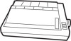
Inserting the interface board 1. Locate the connector cover at the back of the upper case, shown in Figure E-3. Push it down and in, toward the inside of the printer, until it clicks. You need to move the cover to allow access to the new interface connector when the case is reassembled. Figure E-3. connector cover 2. The screw marked CG at the rear of the circuit board is the connection for the frame ground wire. Unscrew it and then use it to connect the frame ground wire as shown in Figure E-4. Figure E-4. Connecting the frame ground wire Choosing and Setting Up Optional Interfaces E-5
-
 1
1 -
2
-
3
-
4
-
5
-
6
-
7
-
8
-
9
-
10
-
11
-
12
-
13
-
14
-
15
-
16
-
17
-
18
-
19
-
20
-
21
-
22
-
23
-
24
-
25
-
26
-
27
-
28
-
29
-
30
-
31
-
32
-
33
-
34
-
35
-
36
-
37
-
38
-
39
-
40
-
41
-
42
-
43
-
44
-
45
-
46
-
47
-
48
-
49
-
50
-
51
-
52
-
53
-
54
-
55
-
56
-
57
-
58
-
59
-
60
-
61
-
62
-
63
-
64
-
65
-
66
-
67
-
68
-
69
-
70
-
71
-
72
-
73
-
74
-
75
-
76
-
77
-
78
-
79
-
80
-
81
-
82
-
83
-
84
-
85
-
86
-
87
-
88
-
89
-
90
-
91
-
92
-
93
-
94
-
95
-
96
-
97
-
98
-
99
-
100
-
101
-
102
-
103
-
104
-
105
-
106
-
107
-
108
-
109
-
110
-
111
-
112
-
113
-
114
-
115
-
116
-
117
-
118
-
119
-
120
-
121
-
122
-
123
-
124
-
125
-
126
-
127
-
 128
128 -
 129
129 -
 130
130 -
 131
131 -
 132
132 -
 133
133 -
 134
134 -
 135
135 -
 136
136 -
 137
137 -
 138
138 -
139
-
140
-
141
-
142
-
143
-
144
-
145
-
146
-
147
-
148
-
149
 |
 |

Inserting the interface board
1. Locate the connector cover at the back of the upper case, shown in
Figure E-3. Push it down and in, toward the inside of the printer,
until it clicks. You need to move the cover to allow access to the
new interface connector when the case is reassembled.
Figure E-3.
connector cover
2. The screw marked CG at the rear of the circuit board is the
connection for the frame ground wire. Unscrew it and then use it to
connect the frame ground wire as shown in Figure E-4.
Figure E-4.
Connecting the frame ground wire
Choosing and Setting Up Optional Interfaces
E-5