Fender Super-Sonic 112 Combo Owners Manual - Page 7
Rear Panel - super sonic 112 guitar combo amp
 |
View all Fender Super-Sonic 112 Combo manuals
Add to My Manuals
Save this manual to your list of manuals |
Page 7 highlights
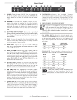
Rear Panel L. POWER-Turns the amp ON-OFF. You can extend the life of the amplifier tubes by keeping the STANDBY {M} switch down for the first 60 seconds that the power is ON. M. STANDBY-In standby, the amplifier outputs are disabled while power is supplied to the tube filaments only, keeping them warm. *Tip: Use STANDBY instead of switching the power off during short breaks to extend tube life and avoid the warm-up delay upon returning to play. N. IEC POWER INPUT SOCKET-Connect to a grounded outlet using the supplied power cord, in accordance with the voltage and frequency specified on the rear panel of your amplifier. O. FUSE-Protects the amplifier from electrical faults. Only replace a blown fuse with the type and rating specified on the rear panel of your amplifier. P. SEND LEVEL-Adjusts the output level of the SEND {Q} jack. Use to accommodate the input sensitivity of your external effects device. Q. SEND / RETURN-Effects loop jacks. Connect SEND to your effects device input and RETURN to the effects output. TIP: The FX button on the footswitch can function as a volume boost switch even without effects in the loop. Simply connect SEND to RETURN with a guitar cable then adjust SEND LEVEL {P} and RETURN LEVEL {R} for the desired level of volume boost. R. RETURN LEVEL-Adjusts the RETURN {Q} jack input level going into the power amp. Use to match the volume level of the amp when effects are off, or to set an alternate volume level selectable from the footswitch. S. PRE AMP OUT-An unbalanced, line-level output (includes Reverb on the 112 Combo amps) suitable for connection to recording equipment and sound systems. NOTE: You can connect this jack to the POWER AMP IN jack on a second Super-Sonic amp for a double amplifier setup. in which you can control both units from the control panel of the primary amplifier. T. POWER AMP IN-A direct input to the power amplifier. The preamp circuit is automatically disconnected when a plug is inserted into this jack. Useful when adding a second Super-Sonic as an extension power amplifier. Connect this jack to PRE AMP OUT from another amp. U. FOOTSWITCH-Connect the included 3-button footswitch to enable remote selection of: Amp Voicing {C}, Channel {E} and FX Loop Bypass. These buttons {C & E} are disabled on the front panel when the footswitch is connected. V. MAIN SPEAKER / EXTENSION SPEAKER- A speaker must ALWAYS be plugged into the MAIN SPKR jack when the Super-Sonic amplifier is ON or damage may occur. Switch the amplifier OFF or to STANDBY while changing speaker connections or impedance settings. • (112 COMBO AMPS)-Keep the internal speaker connected to the MAIN SPKR jack for normal operation. Plug an 8Ω extension speaker into the EXT SPKR jack and the Super-Sonic amplifier will automatically switch to handle a 4Ω load. MAIN SPKR 8Ω + 8Ω + EXT SPKR None 8Ω IMPEDANCE AUTO SETTING = 8Ω = 4Ω • (HEAD AMPS)-Connect speaker enclosures and set the IMPEDANCE SELECTOR {W} according to the table below. MAIN SPKR 16Ω + 16Ω + 8Ω + 8Ω + 4Ω + EXT SPKR None 16Ω None 8Ω None IMPEDANCE SETTING = 16Ω = 8Ω = 8Ω = 4Ω = 4Ω W. IMPEDANCE SELECTOR-(Head Amps) Select the speaker output impedance that matches the total impedance load of the speaker configuration you have chosen from the table above. ◊ ◊ 7
-
 1
1 -
 2
2 -
 3
3 -
 4
4 -
 5
5 -
 6
6 -
 7
7 -
 8
8 -
 9
9 -
 10
10 -
 11
11 -
 12
12 -
13
-
14
-
15
-
16
-
17
-
18
-
19
-
20
-
21
-
22
-
23
-
24
-
25
-
26
-
27
-
28
 |
 |
