Fisher and Paykel DD24DAX9 Installation Manual
Fisher and Paykel DD24DAX9 Manual
 |
View all Fisher and Paykel DD24DAX9 manuals
Add to My Manuals
Save this manual to your list of manuals |
Fisher and Paykel DD24DAX9 manual content summary:
- Fisher and Paykel DD24DAX9 | Installation Manual - Page 1
INSTALLATION INSTRUCTIONS Double DishDrawerTM dishwasher DD24DA & DD24DCT models US CA www.fisherpaykel.com 591153A 07.16 - Fisher and Paykel DD24DAX9 | Installation Manual - Page 2
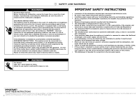
INSTRUCTIONS The models shown in this installation guide may not be available in all markets and are subject to change at any time. For current details about model and specification availability in your country, please go to our 1 website www.fisherpaykel.com or contact your local Fisher & Paykel - Fisher and Paykel DD24DAX9 | Installation Manual - Page 3
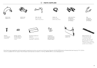
2 PARTS SUPPLIED Drain hose support (1) Drain hose joiner (1) Wire clip (2) (for securing Drain hose joiner) services, you must use a Drain Hose Extension Kit P/N 525798 which will extend the drain hoses by 11' 10" (3.6m). The kit is available from the nearest Fisher & Paykel Authorized Service - Fisher and Paykel DD24DAX9 | Installation Manual - Page 4
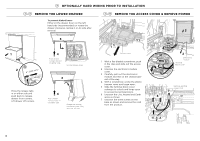
3 OPTIONALLY HARD WIRING PRIOR TO INSTALLATION 3-A REMOVE THE LOWER DRAWER 3-B REMOVE THE ACCESS COVER & REMOVE POWER To prevent kinked hoses Either sit the drawer down on the left hand side (recommended) - Fisher and Paykel DD24DAX9 | Installation Manual - Page 5
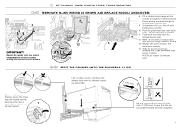
3 OPTIONALLY HARD WIRING PRIOR TO INSTALLATION 3-C TERMINATE MAINS WIRING AS SHOWN AND REPLACE MODULE AND COVERS 12 8 9 13 14 11 IMPORTANT! Ensure the mains wires are routed UNDERNEATH all other harness - Fisher and Paykel DD24DAX9 | Installation Manual - Page 6
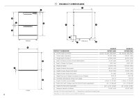
H K I FRONT B E PLAN 5 4 PRODUCT DIMENSIONS C J G A F L PROFILE M N DD24DA DD24DCT PRODUCT DIMENSIONS A Overall height of product1 INCHES (MM) 32 5/16 - 34 5/8" (820-880)2 INCHES (MM) 34 - 36 3/8" (864-924)2 B Overall width of product 23 9/16" (599) 23 9/16" (599) C Overall depth of - Fisher and Paykel DD24DAX9 | Installation Manual - Page 7
5 CABINETRY DIMENSIONS Q R Bracket slots CABINETRY DIMENSIONS P Inside height of cavity* Q Inside width of cavity R Inside depth of cavity S Recommended height of adjacent cabinet space T Height of toekick space* * depending on adjustment of leveling feet PLAN DD24DA INCHES (MM) min. 32 5/16" - Fisher and Paykel DD24DAX9 | Installation Manual - Page 8
cavity. 110-120 VAC max. 15 A ø max. 1 1/2" (38 mm) max. 17 11⁄16" (450 mm) Services hole Can be located either side of dishwasher, preferably at the bottom of the cavity, as shown. If adequate clearance, services hole can be made higher to clear toekick space. If hole is higher, ensure drain - Fisher and Paykel DD24DAX9 | Installation Manual - Page 9
7 MAXIMUM DISTANCE OF HOSES & CORD FROM CHASSIS EDGE LEFT HAND SIDE Drain hoses - 78 1/2" (2000 mm) Inlet hose - 64 3/4" (1650 mm) Power cord (excl.plug) - 29 1/2" (750 mm) RIGHT HAND SIDE Drain hoses - 70 1/2" (1800 mm) Inlet hose - 49" (1250 mm) Power cord (excl.plug) - 27 1/2" (700 mm) 8 - Fisher and Paykel DD24DAX9 | Installation Manual - Page 10
NOW CHOOSE WHICH INSTALLATION METHOD (A) OR (B) IS MORE SUITABLE FOR YOUR CABINETRY... 8 RECOMMENDED METHOD (A) - SECURE WITHOUT DRAWER REMOVAL (FRAMELESS CABINETRY ONLY) 9-A ATTACH SIDE MOUNTING BRACKETS Clip all four side - Fisher and Paykel DD24DAX9 | Installation Manual - Page 11
!1-A SECURE TO THE CABINETRY ON THE SIDES 1 Open the drawer halfway. Using a flat bladed screwdriver, prise the gray rubber plug out of the trim moulding. 2 Replace the gray rubber plug back into the trim moulding and ensure the trim seal is facing forward. 3 !2-A OPTIONALLY SECURE TO THE - Fisher and Paykel DD24DAX9 | Installation Manual - Page 12
8 ALTERNATIVE METHOD (B) - SECURE BY DRAWER REMOVAL 9-B PULL THROUGH HOSES & PUSH INTO THE CAVITY optionally attach the two top mounting brackets (x2) Initially level the product You can raise or lower the product by twisting the feet. Then take care when pushing the product into the cavity that - Fisher and Paykel DD24DAX9 | Installation Manual - Page 13
!1-B SECURE TO THE CABINETRY ON THE SIDES !2-B OPTIONALLY SECURE TO THE CABINETRY ABOVE For further adjustment, using the most appropriate length Hexagonal socket supplied, fully extend leveling feet up to required distance by hand. (x2) The top mounting brackets will only bend upwards a maximum - Fisher and Paykel DD24DAX9 | Installation Manual - Page 14
!4-B FIT THE SUPPLIED TOEKICK PANEL Where the toekick meets the bottom 3 of the tub is the cut-off point 1 Lay the toekick face down on a chopping board or similiar 2 Mark this point on the toekick with a pencil 4 19 Score along the marked cutoff line with a knife 5 19 Turn the toekick over - Fisher and Paykel DD24DAX9 | Installation Manual - Page 15
29 1/2 - 34 3/4" (750-883 mm) !5 THERE ARE THREE DIFFERENT PLUMBING AND DRAINAGE OPTIONS. CHOOSE WHICH IS MORE SUITABLE. DRAINAGE OPTION 1 Dishwasher and Ø 1 1/2" (38 mm) Standpipe Screw Drain hose support to back wall at correct height If space is limited for fixing, push hose through drain hose - Fisher and Paykel DD24DAX9 | Installation Manual - Page 16
DRAINAGE OPTION 2 Dishwasher using Air Break with Drain Hose Joiner Secure both drain hoses to drain hose joiner and secure to Air Break IMPORTANT! Ensure that drain connection - Fisher and Paykel DD24DAX9 | Installation Manual - Page 17
mm) 29 1/2 - 34 3/4" (750-883 mm) DRAINAGE OPTION 3 Dishwasher using drain hose joiner onto sink trap/waste tee Screw Drain hose support to back wall at correct height If space is limited for fixing, push hose through drain hose support to required height 2 max. 4 3/4 po (120 mm) Supplied drain - Fisher and Paykel DD24DAX9 | Installation Manual - Page 18
hoses or drawer latches. ● If a problem occurs, consult the 'Troubleshooting' section of the User guide. ● If after checking these points you still need assistance, please refer to the Service & Warranty book for warranty details and your nearest Authorized Service Center, or contact us through our - Fisher and Paykel DD24DAX9 | Installation Manual - Page 19
joiner must not support the weight of be kept on the dishwasher side of the start guide and section 'Water softener' in the User guide. Model Serial No. Purchase Date Purchaser Dealer Address Installer's Name Installer's Signature Installation Company Installation Date Copyright © Fisher & Paykel - Fisher and Paykel DD24DAX9 | Installation Manual - Page 20
- Fisher and Paykel DD24DAX9 | Installation Manual - Page 21
- Fisher and Paykel DD24DAX9 | Installation Manual - Page 22
INSTALLATION INSTRUCTIONS Single DishDrawerTM dishwasher DD24SA & DD24SCT models US CA www.fisherpaykel.com 591153A 07.16 - Fisher and Paykel DD24DAX9 | Installation Manual - Page 23
INSTRUCTIONS The models shown in this installation guide may not be available in all markets and are subject to change at any time. For current details about model and specification availability in your country, please go to our 1 website www.fisherpaykel.com or contact your local Fisher & Paykel - Fisher and Paykel DD24DAX9 | Installation Manual - Page 24
2 PARTS SUPPLIED Drain hose support (1) Drain hose joiner (1) Wire clip (1) (for securing Drain hose joiner) your services, you must use a Drain Hose Extension Kit P/N 525798 which will extend the drain hoses by 3.6 m. The kit is available from the nearest Fisher & Paykel Authorized Service Center - Fisher and Paykel DD24DAX9 | Installation Manual - Page 25
3 OPTIONALLY HARD WIRING PRIOR TO INSTALLATION 3-A REMOVE THE DRAWER 3-B REMOVE THE ACCESS COVER & REMOVE POWER To prevent kinked hoses Either sit the drawer down on the left hand side (recommended) or - Fisher and Paykel DD24DAX9 | Installation Manual - Page 26
3 OPTIONALLY HARD WIRING PRIOR TO INSTALLATION 3-C TERMINATE MAINS WIRING AS SHOWN AND REPLACE MODULE AND COVERS 12 8 9 13 14 11 IMPORTANT! Ensure the mains wires are routed UNDERNEATH all other harness - Fisher and Paykel DD24DAX9 | Installation Manual - Page 27
F FRONT B E PLAN 5 4 PRODUCT DIMENSIONS C H A I G PROFILE PRODUCT DIMENSIONS A Overall height of product1 D B Overall width of product C Overall depth of product D Depth of chassis (to back of front drawer panel) E Depth of drawer front panel F Height of drawer front panel G Height of - Fisher and Paykel DD24DAX9 | Installation Manual - Page 28
cabinetry Cavity height options allow you to match dishwasher with your cabinetry or companion products DD24SA (Standard height models) K min. 16 1/4" (412mm) Dishwasher K min. 18" (456mm) DD24SCT (Tall (he)ight models) Dishwasher Oven min. 1/2" (13 mm) clearance from a corner cupboard - Fisher and Paykel DD24DAX9 | Installation Manual - Page 29
adjacent to the dishwasher cavity. 110-120 VAC max. 15 A ø max. 1 1/2" (38mm) Services can be located either side of dishwasher. max. 17 to suit 3/8" (9 mm) male Water Pressure Water softener models Max. 1 MPa (145 psi) Min. 0.1 MPa (14.5 psi) Models without water softener Max. 1 MPa (145 psi) Min - Fisher and Paykel DD24DAX9 | Installation Manual - Page 30
7 MAXIMUM DISTANCE OF HOSES & CORD FROM CHASSIS EDGE LEFT HAND SIDE Drain hose - 78 1/2" (2000 mm) Inlet hose - 64 3/4" (1650 mm) Power cord (excl.plug) - 78 1/2" (2000 mm) RIGHT HAND SIDE Drain hose - 70 1/2" (1800 mm) Inlet hose - 49" (1250 mm) Power cord (excl.plug) - 78 1/2" (2000 mm) 8 - Fisher and Paykel DD24DAX9 | Installation Manual - Page 31
NOW CHOOSE WHICH INSTALLATION METHOD (A) OR (B) IS MORE SUITABLE FOR YOUR CABINETRY... 8 RECOMMENDED METHOD (A) - SECURE WITHOUT DRAWER REMOVAL (FRAMELESS CABINETRY ONLY) 9-A B ATTACH SIDE MOUNTING BRACKETS Clip all four side - Fisher and Paykel DD24DAX9 | Installation Manual - Page 32
!1-A SECURE TO THE CABINETRY ON THE SIDES Open the drawer halfway. Using a flat bladed screwdriver, prise the grey rubber plug out of the trim moulding. 2 Using a small Philips screwdriver, screw through the trim moulding, securing the side mounting bracket to the cabinetry. Do not damage the - Fisher and Paykel DD24DAX9 | Installation Manual - Page 33
8 ALTERNATIVE METHOD (B) - SECURE BY DRAWER REMOVAL 9-B PULL THROUGH HOSES & PUSH INTO THE CAVITY As you push product in, pull through hoses and cord, ensuring they don't get kinked or twisted. IMPORTANT! If product cannot be pushed in far enough, pull out again and rearrange hoses and cord. Do not - Fisher and Paykel DD24DAX9 | Installation Manual - Page 34
!1-B SECURE TO THE CABINETRY ON THE SIDES The product has three pairs of fixing points: Ensure the sound insulation is repositioned correctly. two pairs of formed brackets on either side of the chassis (use 5/8" (16mm) screws) 2 Before refitting the drawer, ensure the hoses are not twisted and - Fisher and Paykel DD24DAX9 | Installation Manual - Page 35
1/2 - 34 3/4" (750 - 883mm) !3 THERE ARE THREE DIFFERENT PLUMBING AND DRAINAGE OPTIONS. CHOOSE WHICH IS MORE SUITABLE. DRAINAGE OPTION 1 Dishwasher and Ø 1 1/2" (38 mm) Standpipe Screw Drain hose support to back wall at correct height If space is limited for fixing, push hose through drain hose - Fisher and Paykel DD24DAX9 | Installation Manual - Page 36
DRAINAGE OPTION 2 Dishwasher using Air Break with Drain Hose Joiner Secure drain hose to drain hose joiner and secure to Air Break 2 IMPORTANT! Ensure that drain connection will - Fisher and Paykel DD24DAX9 | Installation Manual - Page 37
regulations. 15 29 1/2"- 34 3/4" (750 - 882.5mm) min. 19 11/16" (500mm) 29 1/2 - 34 3/4" (750 - 883mm) DRAINAGE OPTION 3 Dishwasher using drain hose joiner onto sink trap/waste tee Screw Drain hose support to back wall at correct height If space is limited for fixing, push hose through drain hose - Fisher and Paykel DD24DAX9 | Installation Manual - Page 38
!4 CONNECT INLET HOSE TO HOT WATER Ensure the supplied rubber washer is fitted inside the coupling. 1 180o No leaks! Tighten coupling with spanner. 2 !5 SWITCH PRODUCT ON 16 - Fisher and Paykel DD24DAX9 | Installation Manual - Page 39
hoses or drawer latches. ● If a problem occurs, consult the 'Troubleshooting' section of the User guide. ● If after checking these points you still need assistance, please refer to the Service & Warranty book for warranty details and your nearest Authorized Service Center, or contact us through our - Fisher and Paykel DD24DAX9 | Installation Manual - Page 40
joiner must not support the weight of be kept on the dishwasher side of the start guide and section 'Water softener' in the User guide. Model Serial No. Purchase Date Purchaser Dealer Address Installer's Name Installer's Signature Installation Company Installation Date Copyright © Fisher & Paykel
-
 1
1 -
 2
2 -
 3
3 -
 4
4 -
 5
5 -
 6
6 -
 7
7 -
8
-
9
-
10
-
11
-
12
-
13
-
14
-
15
-
16
-
17
-
18
-
19
-
20
-
21
-
22
-
23
-
24
-
25
-
26
-
27
-
28
-
29
-
30
-
31
-
32
-
33
-
34
-
35
-
36
-
37
-
38
-
39
-
40
 |
 |

Double DishDrawer
TM
dishwasher
DD24DA & DD24DCT
models
US CA
INSTALLATION INSTRUCTIONS
591153A
07.16
www.fisherpaykel.com