Fisher and Paykel DD24DAX9 Installation Manual - Page 7
Cabinetry Dimensions
 |
View all Fisher and Paykel DD24DAX9 manuals
Add to My Manuals
Save this manual to your list of manuals |
Page 7 highlights
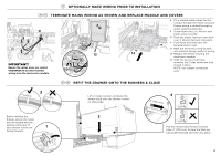
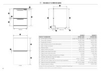
5 CABINETRY DIMENSIONS Q R Bracket slots CABINETRY DIMENSIONS P Inside height of cavity* Q Inside width of cavity R Inside depth of cavity S Recommended height of adjacent cabinet space T Height of toekick space* * depending on adjustment of leveling feet PLAN DD24DA INCHES (MM) min. 32 5/16" (820) 23 5/8" (600) min. 22 1/16" (560) 30" (762) 2 3/8 - 4 3/4" (60-120) DD24DCT INCHES (MM) min. 34" (864) 23 5/8" (600) min. 22 1/16" (560) 30" (762) 3 15/16" - 6 5/16" (100-160) P S T PROFILE Minimum clearances from adjacent cabinetry min. 1/2" (13 mm) clearance from a corner cupboard min. 1/16" (2 mm) clearance to adjacent cupboard door 6
-
 1
1 -
 2
2 -
 3
3 -
 4
4 -
 5
5 -
 6
6 -
 7
7 -
 8
8 -
 9
9 -
 10
10 -
 11
11 -
 12
12 -
13
-
14
-
15
-
16
-
17
-
18
-
19
-
20
-
21
-
22
-
23
-
24
-
25
-
26
-
27
-
28
-
29
-
30
-
31
-
32
-
33
-
34
-
35
-
36
-
37
-
38
-
39
-
40
 |
 |

6
5
CABINETRY DIMENSIONS
Minimum clearances from adjacent cabinetry
min. 1/2” (13 mm)
clearance from a
corner cupboard
Bracket slots
min. 1/16” (2 mm)
clearance
to adjacent
cupboard door
R
Q
P
S
T
PROFILE
PLAN
DD24DA
DD24DCT
CABINETRY DIMENSIONS
INCHES (MM)
INCHES (MM)
P
Inside height of cavity*
min. 32 5/16”
(820)
min. 34”
(864)
Q
Inside width of cavity
23 5/8”
(600)
23 5/8”
(600)
R
Inside depth of cavity
min. 22 1/16”
(560)
min. 22 1/16”
(560)
S
Recommended height of adjacent cabinet space
30”
(762)
30”
(762)
T
Height of toekick space*
2 3/8 - 4 3/4” (60-120)
3 15/16” - 6 5/16” (100-160)
* depending on adjustment of leveling feet