Fluke 287 Fluke 287 and 289 Multimeter Users Manual
Fluke 287 Manual
 |
View all Fluke 287 manuals
Add to My Manuals
Save this manual to your list of manuals |
Fluke 287 manual content summary:
- Fluke 287 | Fluke 287 and 289 Multimeter Users Manual - Page 1
® 287/289 True-rms Digital Multimeters June 2007, Rev. 1, 7/08 © 2007, 2008 Fluke Corporation. All rights reserved. Specifications subject to change without notice. All product names are trademarks of their respective companies. Users Manual - Fluke 287 | Fluke 287 and 289 Multimeter Users Manual - Page 2
authorized sales outlet and at the applicable international price. Fluke reserves the right to charge for importation costs of repair/replacement parts if the product purchased in one country is sent for repair elsewhere. If the product is defective, contact your nearest Fluke authorized service - Fluke 287 | Fluke 287 and 289 Multimeter Users Manual - Page 3
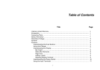
Table of Contents Title Page Lifetime Limited Warranty ii Introduction ...1 Contacting Fluke ...1 Safety Information ...1 Hazardous Voltage...3 Symbols ...4 Features ...5 Understanding Labels ...9 Adjusting Display Contrast 9 Understanding the Rotary Switch 10 Using the Input Terminals 11 i - Fluke 287 | Fluke 287 and 289 Multimeter Users Manual - Page 4
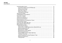
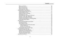
287/289 Users Manual Controlling Meter Power 12 Powering the Meter On and Off Manually 12 Battery Level Indicator 12 Automatic Power-Off 12 Battery Saver Mode 12 Controlling the Backlight 13 Selecting the Range ...13 Understanding Function Menus 13 Input Alert™ Feature...15 Using the Info - Fluke 287 | Fluke 287 and 289 Multimeter Users Manual - Page 5
the Meter's Language 47 Setting Date and Time 48 Setting Backlight and Auto Off Timeouts 48 Setting a Custom dBm Reference 48 Disabling and Enabling the Beeper 48 Enabling and Disabling the Smoothing Mode 49 Using Other Setup Options 49 Using Memory ...49 Storing Individual Measurement Data - Fluke 287 | Fluke 287 and 289 Multimeter Users Manual - Page 6
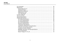
287/289 Users Manual Error Messages ...56 Maintenance ...57 General Maintenance 57 Testing the Fuses...57 Replacing the Batteries 59 Replacing the Fuses 59 Test Lead Storage...59 In Case of Difficulty ...61 Service and Parts ...62 General Specifications 66 Detailed Specifications 67 AC Voltage - Fluke 287 | Fluke 287 and 289 Multimeter Users Manual - Page 7
2. Push Buttons ...5 3. Display Features ...7 4. Rotary Switch Positions...10 5. Input Terminals...11 6. Battery Level Indicator...12 7. Trend Data Display...51 8. Recording Display ...53 9. Stopped Recording Display 55 10. Error Messages ...56 11. Replacement Parts ...62 12. Accessories ...65 v - Fluke 287 | Fluke 287 and 289 Multimeter Users Manual - Page 8
287/289 Users Manual vi - Fluke 287 | Fluke 287 and 289 Multimeter Users Manual - Page 9
List of Figures Figure Title Page 1. Push Buttons ...5 2. Display Features ...7 3. Rotary Switch ...10 4. Input Terminals...11 5. Function Menu...14 6. MIN MAX Record Display...17 7. Peak Record Display 15. Resistance Measurement...30 16. Continuity Indicator...31 17. Continuity Testing...32 vii - Fluke 287 | Fluke 287 and 289 Multimeter Users Manual - Page 10
287/289 Users Manual 18. Conductance Measurement 34 19. Capacitance Measurement 35 20. Diode Testing...37 21. Current Measurement Setup Pulse Width Measurements 46 28. Testing the Current Fuses...58 29. Test Lead Storage ...59 30. Replacing Batteries and Fuses 60 31. Replaceable Parts...64 viii - Fluke 287 | Fluke 287 and 289 Multimeter Users Manual - Page 11
"Safety Information" before using this Meter. The descriptions and instructions in this manual apply to the model 289 and model 287 True-rms Digital Multimeters (hereafter referred to as the Meter). The model 289 appears in all illustrations. Contacting Fluke To contact Fluke, call: USA: 1-888-993 - Fluke 287 | Fluke 287 and 289 Multimeter Users Manual - Page 12
287/289 Users Manual • Make sure the battery door is closed and latched before operating the Meter. • Remove test leads from the Meter before opening the battery door. • Inspect the test leads for damaged insulation or exposed metal. Check the test leads for continuity. Replace damaged test leads - Fluke 287 | Fluke 287 and 289 Multimeter Users Manual - Page 13
for all measurements. True-rms Digital Multimeters Hazardous Voltage • Do not remove batteries while the Meter is turned on or a signal is applied to the Meter's input jacks. • Before measuring current, check the Meter's fuses. (See "Testing the Fuses" in the Users Manual on the accompanying CD - Fluke 287 | Fluke 287 and 289 Multimeter Users Manual - Page 14
287/289 Users Manual Symbols Table 1 lists and describes the symbols used on the Meter and in this manual. Table 1. Symbols Symbol B F X E R P t CAT III ~ Description Symbol Description AC (Alternating Current or Voltage) DC (Direct Current or Voltage) I Fuse T Double Insulated Hazardous - Fluke 287 | Fluke 287 and 289 Multimeter Users Manual - Page 15
Push Buttons est02.emf True-rms Digital Multimeters Features Table 2. Push Buttons Button O Function Turns the Meter on or off. 12 data entry. H Freezes the present reading in the display and allows the display to be saved. Also accesses AutoHold. R M Switches the Meter range mode to manual - Fluke 287 | Fluke 287 and 289 Multimeter Users Manual - Page 16
287/289 Users Manual Using Auto Repeat For some menu selections, holding down a softkey or cursor button will continuously change (or advance) a faster if the button is held for two or more seconds. This is helpful when scrolling through a list of selections, such as a list of stored measurements. 6 - Fluke 287 | Fluke 287 and 289 Multimeter Users Manual - Page 17
16 AutoHOLD Save 1 Setup Figure 2. Display Features est01.eps True-rms Digital Multimeters Features Table 3. Display Features Item Function A Softkey labels B at the Meter's input. Indicates activity over the communication link. Indicates the charge level of the six AA batteries. Indicates - Fluke 287 | Fluke 287 and 289 Multimeter Users Manual - Page 18
287/289 Users Manual Table 3. Display Features (cont.) Item Function Indication J Minimeasurement Displays the lightning bolt (when necessary) and the input value when the primary and secondary displays are covered by a menu or pop-up message. K Date Indicates the date set in the internal - Fluke 287 | Fluke 287 and 289 Multimeter Users Manual - Page 19
of the display. These labels will change based on the function and/or menu selection. Adjusting Display Contrast When not selecting items on a menu or inputting data, pressing 7 increases display contrast and pressing 8 decreases it. True-rms Digital Multimeters Features 9 - Fluke 287 | Fluke 287 and 289 Multimeter Users Manual - Page 20
a low input impedance (model 289 only) V AC voltage measurements T AC millivolt measurements U DC and ac+dc voltage measurements N S P DC millivolts, ac+dc millivolt, and temperature measurements Resistance, continuity, and conductance measurements Diode test and capacitance measurements - Fluke 287 | Fluke 287 and 289 Multimeter Users Manual - Page 21
. True-rms Digital Multimeters Features Table 5. Input Terminals Terminal Description Input for Input for 0 A to 400 mA current measurements, frequency, and duty cycle. COM Return terminal for all measurements. Input for voltage, continuity, resistance, diode test, conductance, capacitance - Fluke 287 | Fluke 287 and 289 Multimeter Users Manual - Page 22
287/289 Users Manual Controlling Meter Power The Meter is powered by six AA batteries and controlled through a front panel power switch and internal circuits designed to help conserve battery power. The following sections describe several techniques for controlling Meter power. Powering the Meter On - Fluke 287 | Fluke 287 and 289 Multimeter Users Manual - Page 23
not support the backlight operation. To conserve battery life, a user-adjustable timeout controls how long the backlight stays on. The default timeout is 5 minutes. To change the timeout, refer to "Setting Backlight and Auto Off Timeouts" later in this manual. True-rms Digital Multimeters Selecting - Fluke 287 | Fluke 287 and 289 Multimeter Users Manual - Page 24
287/289 Users Manual VAC REL Peak, CF Menu Hz, %, mS dBm dBV REL REL% Close Pressing the softkey labeled Close closes the pop-up menu, leaving the Meter in the state it was in before pressing the Menu softkey. 14 In most cases, the softkeys revealed by the menu selection act like toggles. The - Fluke 287 | Fluke 287 and 289 Multimeter Users Manual - Page 25
is pressed. Each topic provides a brief explanation on a Meter function or feature. True-rms Digital Multimeters Input Alert™ Feature The information revealed through I is not meant to replace the more detailed information found in this manual. Function and feature explanations are brief and only - Fluke 287 | Fluke 287 and 289 Multimeter Users Manual - Page 26
287/289 Users Manual out open lead conditions so the Meter leads can be moved between test points without triggering a display update. Note For temperature measurements, the AutoHold threshold is a percent of 100 degrees. The default AutoHold threshold is 4% of 100 degrees, or 4 degrees Celsius or - Fluke 287 | Fluke 287 and 289 Multimeter Users Manual - Page 27
6, the Meter displays e at the top of the measurement page, and the MIN MAX start date and time along the bottom of the page. In addition, the recorded maximum, average, and minimum values appear in the secondary display with their respective elapsed times. True-rms Digital Multimeters Capturing - Fluke 287 | Fluke 287 and 289 Multimeter Users Manual - Page 28
287/289 Users Manual the softkey labeled Save to store the MIN MAX screen data. MIN MAX can not be continued at this point. Press the softkey labeled Close to exit the MIN MAX mode. Pressing the softkey labeled Restart while MIN MAX is running stops the MIN MAX session, discards all MIN MAX data, - Fluke 287 | Fluke 287 and 289 Multimeter Users Manual - Page 29
the Peak screen data. Peak capture can battery life during peak record, the Meter enters a battery-saver mode after a period of time set for the Auto Off feature. See the "Setting Backlight and Auto Off Timeouts" section for more information on the battery saver mode. True-rms Digital Multimeters - Fluke 287 | Fluke 287 and 289 Multimeter Users Manual - Page 30
287/289 Users Manual Low Pass Filter (Model 289 only) The Meter is equipped with an ac low pass filter. generated by inverters and variable frequency motor drives. Note In Low Pass Mode, the Meter goes to manual mode. Select ranges by pressing R. Autoranging is not available when the Low Pass Filter - Fluke 287 | Fluke 287 and 289 Multimeter Users Manual - Page 31
Meter displayed in the True-rms Digital Multimeters Making Relative Measurements Meter displays OL. With the exception of dB measurements, ranging is set to manual and can not be changed. Both auto and manual button acts as a toggle, switching the Meter between the two modes. Moving the rotary - Fluke 287 | Fluke 287 and 289 Multimeter Users Manual - Page 32
287/289 Users Manual Making Measurements The following sections describe how to take measurements with the Meter. Measuring AC Voltage The Meter displays ac voltage measurements as rms (root mean square) readings. The rms value is the equivalent dc voltage that would produce the same amount of heat - Fluke 287 | Fluke 287 and 289 Multimeter Users Manual - Page 33
Measurements The Meter is capable of displaying voltage as a dB value, either relative to 1 milliwatt (dBm), a reference voltage of 1 volt (dBV) or a user-selectable reference value. See the "Setting a Custom dBm Reference" section later in this manual. 8:10pm True-rms Digital Multimeters Making - Fluke 287 | Fluke 287 and 289 Multimeter Users Manual - Page 34
287/289 Users Manual To select another reference value, press the softkey labeled Ref to display as a dBV value. The reference impedance setting is not part of a dBV measurement. To make a dBV measurement, position the rotary switch to V or T and place the Meter leads on the voltage to be measured. - Fluke 287 | Fluke 287 and 289 Multimeter Users Manual - Page 35
in this manual to learn more about each menu item. To clear all modes and return to the basic volts dc measurement, press the softkey labeled Menu. Move the menu selector to the item labeled VDC. Press the softkey labeled VDC to clear all functions and modes. True-rms Digital Multimeters Making - Fluke 287 | Fluke 287 and 289 Multimeter Users Manual - Page 36
287/289 Users Manual Measuring AC and DC Signals The Meter is capable of displaying both ac and dc signal components (voltage or current) as two separate readings or one AC+DC (rms) value combined. As shown in Figure 13, the Meter displays ac and dc combinations three ways: ac displayed over dc (AC - Fluke 287 | Fluke 287 and 289 Multimeter Users Manual - Page 37
softkey labeled VDC. For the current functions, move the menu selector to the AC,DC menu item and press either the AC or DC softkey. True-rms Digital Multimeters Making Measurements 27 - Fluke 287 | Fluke 287 and 289 Multimeter Users Manual - Page 38
287/289 Users Manual Measuring Temperature XW Warning To avoid the potential for fire or electric shock, do not connect the thermocouple to electrically live circuits. The Meter uses an 80BK-A Integrated DMM Temperature Probe or other type-K temperature probe for measuring temperature. To measure - Fluke 287 | Fluke 287 and 289 Multimeter Users Manual - Page 39
(Ω). This is accomplished by sending a small current out through the test leads to the circuit under test. To measure resistance, set the Meter's rotary switch to S and set up the Meter as shown in Figure 15. True-rms Digital Multimeters Making Measurements Keep the following in mind when measuring - Fluke 287 | Fluke 287 and 289 Multimeter Users Manual - Page 40
287/289 Users Manual 8:10pm 06/13/07 5.67 Auto Range 0 100 200 300 400 500 Menu Save Setup In-Circuit Resistance Measurements Circuit Power OFF Isolating a Potentiometer 1 3 2 Disconnect 1 2 3 Isolating a Resistor Disconnect Figure 15. Resistance Measurement est11.eps 30 - Fluke 287 | Fluke 287 and 289 Multimeter Users Manual - Page 41
ohms function measurement. However, for continuity transitions that are very short, the slow True-rms Digital Multimeters Making Measurements measurement response of the Meter will not appear in the digital display. Therefore, the continuity function uses a graphical indicator for the presence or - Fluke 287 | Fluke 287 and 289 Multimeter Users Manual - Page 42
287/289 Users Manual For in-circuit tests, turn circuit power off. Beep on short 8:10pm 06/13/07 5.67 Continuity 0 100 200 300 400 500 Beep on 0 100 200 300 400 500 Beep on OPEN Menu Save Setup ON (closed) ON (closed) OFF (open) Figure 17. Continuity Testing est13.eps 32 - Fluke 287 | Fluke 287 and 289 Multimeter Users Manual - Page 43
enabled and i when disabled. This setting is independent of the Meter's beeper enable/disable setting in the setup menu. Toggle between the continuity and ohms functions by pressing softkey F3, which is always labeled with the alternate function. True-rms Digital Multimeters Making Measurements 33 - Fluke 287 | Fluke 287 and 289 Multimeter Users Manual - Page 44
287/289 Users Manual Using Conductance for High Resistance Tests Conductance, the inverse of resistance, is the ability of a circuit to pass current. High values of conductance correspond to low values of resistance. The unit of conductance is the Siemens (S). The meter's 50 nS range measures - Fluke 287 | Fluke 287 and 289 Multimeter Users Manual - Page 45
in the nanofarad (nF) to microfarad (μF) range. The Meter measures capacitance by charging the capacitor with a known current for a known period of time, measuring the resulting voltage, and then calculating the capacitance. True-rms Digital Multimeters Making Measurements 8:10pm 06/13/07 26.52 - Fluke 287 | Fluke 287 and 289 Multimeter Users Manual - Page 46
287/289 Users Manual To measure capacitance, position the rotary switch to P and set up the Meter as shown in Figure 19. If the display doesn't already indicate the Meter is measuring capacitance, press the softkey labeled Menu. Next, move the menu selector to the menu item labeled Diode,Cap and - Fluke 287 | Fluke 287 and 289 Multimeter Users Manual - Page 47
True-rms Digital Multimeters Making Measurements 8:10pm 06/13/07 .567 VDC Manual Range 0 1 2 3 4 5 VDC Menu Save Setup Typical Reading Forward Bias + 8:10pm 06/13/07 OL VDC Manual Range 0 1 2 3 4 5 VDC Menu Save Setup Reverse Bias + Figure 20. Diode Testing est16.eps 37 - Fluke 287 | Fluke 287 and 289 Multimeter Users Manual - Page 48
287/289 Users Manual Measuring Current XW Warning To avoid damage to the Meter and possible injury, never attempt an in-circuit current measurement where the open-circuit potential to earth is greater than 1000 V. W Caution To avoid possible damage to the Meter or to the equipment under test, check - Fluke 287 | Fluke 287 and 289 Multimeter Users Manual - Page 49
function, the Meter will stay in the selected AC or DC current measurement mode when switching between n and €. Whenever switched to one of the current measurement functions, the Meter will default to the last current type selected (AC or DC). True-rms Digital Multimeters Making Measurements 39 - Fluke 287 | Fluke 287 and 289 Multimeter Users Manual - Page 50
287/289 Users Manual 8:10pm 06/13/07 2.5527 AAC Auto Range 0 1 2 3 4 5 AAC Menu Save Setup 8:10pm 06/13/07 19.783 mAAC Auto Range 0 1 2 3 4 5 AAC Menu Save Setup 8: - Fluke 287 | Fluke 287 and 289 Multimeter Users Manual - Page 51
8:10pm 06/13/07 mAAC Circuit Power: OFF to connect meter. ON for measurement. OFF to disconnect meter. True-rms Digital Multimeters Making Measurements Total current to circuit Current through one component Figure 22. Current Measurement Circuit Connection est19.eps 41 - Fluke 287 | Fluke 287 and 289 Multimeter Users Manual - Page 52
287/289 Users Manual W Caution Placing the probes across (in parallel with) a powered circuit when a lead is plugged into a current terminal can damage the circuit you are testing and blow the Meter's fuse. This can happen because the resistance through the Meter's current terminals is very low, so - Fluke 287 | Fluke 287 and 289 Multimeter Users Manual - Page 53
the volts or amps value of the input signal. True-rms Digital Multimeters Making Measurements Selection between a rising trigger problems by manually selecting a lower input range, which increases the sensitivity of the meter. If a reading seems to be a multiple of what you expect, the input - Fluke 287 | Fluke 287 and 289 Multimeter Users Manual - Page 54
287/289 Users Manual Measures Positive Pulse Trigger Level 30% Above Trigger Level 100% Measures Negative Pulse Trigger Level 70% Below Trigger Level 100% Figure 25. Duty Cycle Measurements 44 est28.eps - Fluke 287 | Fluke 287 and 289 Multimeter Users Manual - Page 55
-measurement display indicates the True-rms Digital Multimeters Making Measurements volts or amps value of the input signal. The bar graph result in multiple triggering. A manually-selected lower input range will often measure better than the AUTO-selected input range. Measuring Pulse Width The - Fluke 287 | Fluke 287 and 289 Multimeter Users Manual - Page 56
287/289 Users Manual Trigger Level 46 Measure Positive Pulse Width Pulse Width 1 Period = Frequency Measure Negative Pulse Width Trigger Level Pulse Width Period Figure 27. Pulse Width Measurements est27.eps - Fluke 287 | Fluke 287 and 289 Multimeter Users Manual - Page 57
indicates the volts or amps value of the input signal. The bar graph tracks the volts or Meter Setup Options The Meter has a number of preset features such as date and time formats, backlight and battery to perform the reset. True-rms Digital Multimeters Changing Meter Setup Options Note A setup - Fluke 287 | Fluke 287 and 289 Multimeter Users Manual - Page 58
287/289 Users Manual Setting Date and Time The Meter automatically turn the Meter off or enable the battery saver mode. on a specific digit. Press 7 and 8 to increment or decrement the digit. With Testing for Continuity" section for information on the continuity beeper. To enable or disable the Meter - Fluke 287 | Fluke 287 and 289 Multimeter Users Manual - Page 59
Security regulations. Meter calibration is not lost when this low-level erase is performed. As new Meter features are created, the latest version of software can be downloaded to the Meter from Fluke's support web page using the Software Update option. True-rms Digital Multimeters Using Memory - Fluke 287 | Fluke 287 and 289 Multimeter Users Manual - Page 60
287/289 Users Manual session, press the softkey labeled Save. To select the name from the preset list, press +Name. To save to the same name as before but with the Next press the softkey labeled Save. Viewing Memory Data Viewing data stored in the Meter's memory is performed through the save menu. - Fluke 287 | Fluke 287 and 289 Multimeter Users Manual - Page 61
True-rms Digital Multimeters Using Memory E Elapsed time. Units in hours and minutes, or minutes and seconds. F Time scale legend (HH:MM or MM:SS) G Measured value and timestamp of selected record. Zooming in on Trend Data While viewing trend data Data Deleting data stored in the Meter's - Fluke 287 | Fluke 287 and 289 Multimeter Users Manual - Page 62
287/289 Users Manual softkeys labeled Prev and Next to select an item for deletion. Next, press the softkey labeled Delete. A message asking to confirm the deletion will appear before anything is deleted from memory. Recording Measurement Data The Meter's record feature collects measurement - Fluke 287 | Fluke 287 and 289 Multimeter Users Manual - Page 63
Meter for the measurements to be recorded. If needed, change the event threshold value (see the "Setting the Event Threshold Value section later in this manual minute to 99 days 23 hours 59 minutes. True-rms Digital Multimeters Recording Measurement Data Table 8. Recording Display 8:10pm 123.45 - Fluke 287 | Fluke 287 and 289 Multimeter Users Manual - Page 64
287/289 Users Manual The Meter allocates memory in such a way as to guarantee capturing all of the user-specified sample intervals. Event records will also be captured until the Meter and set each digit of the selected variable. If the battery level is anything but data (see the "Viewing Trend Data" - Fluke 287 | Fluke 287 and 289 Multimeter Users Manual - Page 65
True-rms Digital Multimeters Using Communications Using Communications You can use the IR communication link and FlukeView Forms software to transfer the contents of a meter's memory to a PC. When using a PC-to-meter IR (infrared) communication link, refer to the FlukeView Forms Installation Guide - Fluke 287 | Fluke 287 and 289 Multimeter Users Manual - Page 66
287/289 Users Manual Error Messages Table 10 list some of the error messages the Meter may display and the conditions that may be causing the error. Table 10. Error Messages Message Conditions Leads connected incorrectly. Lead in A or mA/μA jack but rotary switch not in corresponding A/mA or - Fluke 287 | Fluke 287 and 289 Multimeter Users Manual - Page 67
and detergent out of the terminals. True-rms Digital Multimeters Maintenance Testing the Fuses As shown in Figure 28, with the Meter in the S function, insert a test lead into the W jack and place the probe tip on the other end of the test lead against the metal of the current input jack. If the - Fluke 287 | Fluke 287 and 289 Multimeter Users Manual - Page 68
287/289 Users Manual 8:10pm 06/13/07 10.000 k Menu Replace F1 if reading is OL 8:10pm 06/13/07 0.50 Menu Replace F2 if reading is OL Figure 28. Testing the Current Fuses est33.eps 58 - Fluke 287 | Fluke 287 and 289 Multimeter Users Manual - Page 69
shown in Table 11. 5. Reinstall the battery door assembly and secure it by turning the screw one-half turn clockwise. True-rms Digital Multimeters Maintenance Test Lead Storage Figure 29 shows the proper method for storing the test leads with the Meter. Figure 29. Test Lead Storage est41.eps 59 - Fluke 287 | Fluke 287 and 289 Multimeter Users Manual - Page 70
287/289 Users Manual F2 11 A F1 0.44 A Figure 30. Replacing Batteries and Fuses est32.eps 60 - Fluke 287 | Fluke 287 and 289 Multimeter Users Manual - Page 71
(as needed) the batteries, fuses, and test leads. 4. Review this manual to verify correct operation. 5. If the Meter still does not work, pack it securely and forward it, postage paid, to the location provided by the appropriate Fluke contact. Include a description of the problem. Fluke assumes no - Fluke 287 | Fluke 287 and 289 Multimeter Users Manual - Page 72
287/289 Users Manual Service and Parts Replacement parts and accessories are shown in Tables 11 and 12 and Figure 31. To order parts and accessories, refer to the "Contacting Fluke" section. Item 1 2 3 4 5 6 7 8 9 10 11 12 Knob Skin Keypad O-Ring Case Top Screw, Phillps Mask, LCD LCD Module - Fluke 287 | Fluke 287 and 289 Multimeter Users Manual - Page 73
True-rms Digital Multimeters Service and Parts Table 11. Replacement Parts (cont.) Item Description Qty. Fluke Part/Model Number 13 RSOB Housing, Lower 1 2578290 14 Case Bottom 1 2578184 15 Shock Absorber, Battery Compartment 1 2793525 16 Battery Contact, Negative 2 2578375 17 - Fluke 287 | Fluke 287 and 289 Multimeter Users Manual - Page 74
287/289 Users Manual 1 2 3 4 5 6 7 4 PL 8 2 PL 9 10 11 12 13 64 14 15 18 19 20 21 23 16 25 17 22 6 PL Figure 31. Replaceable Parts 24 26 est40.eps - Fluke 287 | Fluke 287 and 289 Multimeter Users Manual - Page 75
Test Leads TL220 Industrial Test Lead Set TL224 Test Lead Set, Heat-Resistant Silicone TP1 Test Probes, Flat Blade, Slim Reach TP4 Test Probes, 4 mm diameter, Slim Reach Fluke accessories are available from an authorized Fluke distributor. True-rms Digital Multimeters Service and Parts - Fluke 287 | Fluke 287 and 289 Multimeter Users Manual - Page 76
289 Users Manual General Specifications Maximum voltage between any Terminal and Earth Ground: 1000 V W Fuse Protection for mA or μA inputs 0.44 A (44/100 A, 440 mA), 1000 V FAST Fuse, Fluke specified part only W Fuse Protection for A input 11 A, 1000 V FAST Fuse, Fluke specified part only Battery - Fluke 287 | Fluke 287 and 289 Multimeter Users Manual - Page 77
True-rms Digital Multimeters Detailed Specifications Electromagnetic Compatibility Standards (EMC) European EMC EN61326-1 Australian EMC N10140 US FCC FCC CFR47: Part 15 CLASS A Certifications UL, CE, CSA, ; (N10140), s Detailed Specifications Accuracy: Accuracy is specified for a period of one - Fluke 287 | Fluke 287 and 289 Multimeter Users Manual - Page 78
287/289 Users Manual AC Voltage Specifications dB 0.1 dB 2 % + 40 Accuracy 65 Hz to 10 kHz 0.4 % Spec'd Not Spec'd 3 dB 2 dB 0.8 dB 0.8 dB Not Spec'd Not Spec'd L [4] 1000 V 0.1 V 2 % + 80 2 % + 40 2 % + 40 [7] Not Spec'd Not Spec'd [1] Below 5 % of range, add 20 counts. [2] Specification - Fluke 287 | Fluke 287 and 289 Multimeter Users Manual - Page 79
on, 1 minute off. [4] Verified by design and type tests. See Detailed Specifications introduction for additional information. 20 to 45 Hz 1 % + 20 1 % + 5 1 % + 20 1 % + 5 1.5 % + 20 1.5 % + 5 True-rms Digital Multimeters Detailed Specifications Accuracy 45 to 1 kHz 1 to 20 kHz 0.6 % + 20 - Fluke 287 | Fluke 287 and 289 Multimeter Users Manual - Page 80
287/289 Users Manual DC Voltage Specification Function DC mV DC V [1] L [1] Range 50 mV [3] 500 mV 5 V 50 V 500 V 1000 V 1000 V Resolution 0.001 mV 0.01 mV 0.0001 V 0.001 V 0.01 V 0.1 V 0.1 V DC[2] 0.05 % + 20 [4] 0.025 % + 2 [5] 0.025 % + 2 0.025 % + 2 0.03 % + 2 0.03 % + 2 1 % + 20 Accuracy - Fluke 287 | Fluke 287 and 289 Multimeter Users Manual - Page 81
True-rms Digital Multimeters Detailed Specifications DC Current Specifications Function DC μA [4] Range 500 μA Resolution 0.01 μA DC[1][3] 0.075 % + 20 Accuracy % + 40 Not Spec'd Not Spec'd [1] AC+DC tests. [6] Temperature coefficient: 0.1 X (specified accuracy)/ °C ( 28 °C) 71 - Fluke 287 | Fluke 287 and 289 Multimeter Users Manual - Page 82
287/289 Users Manual Resistance Specifications Function Resistance 50 Ω [1][3] 500 Specifications Temperature Resolution Accuracy [1,2] -200 °C to +1350 °C 0.1 °C 1 % + 10 -328 °F to +2462 °F 0.1 °F 1 % + 18 [1] Does not include error of the thermocouple probe. [2] Accuracy specification - Fluke 287 | Fluke 287 and 289 Multimeter Users Manual - Page 83
Resolution 0.001 nF 0.01 nF 0.1 nF 1 μF 0.001 μF 10 μF 0.01 μF Diode Test 100 μF 1000 μF 10 mF 100 mF 3.1 V 0.1 μF 1 μF 0.01 mF 0.1 mF 0.0001 V [1] With a film capacitor or better, using relative mode (REL Δ) to zero residual. True-rms Digital Multimeters Detailed Specifications Accuracy - Fluke 287 | Fluke 287 and 289 Multimeter Users Manual - Page 84
287/289 Users Manual Frequency Counter Specifications Function Range Resolution Accuracy Frequency (0.5 0.01 ms 0.002 ms + 3 counts 1999.9 ms 0.1 ms 0.002 ms + 3 counts [1] For 64.000 kHz to 67.000 kHz, accuracy = ±5 Hz, at -20 to +55 °C with R.H. 0 % to 90 % (0 °C to 37 °C), 0 % to 65 % ( - Fluke 287 | Fluke 287 and 289 Multimeter Users Manual - Page 85
True-rms Digital Multimeters Detailed Specifications Frequency Counter Sensitivity Input Range Approximate Voltage Sensitivity (rms sine wave) [1] 15 Hz to 100 kHz AC Bandwidth [2] Approximate DC Trigger Levels DC Bandwidth [2] 50 mV 500 mV 5 mV 25 mV 1 MHz 1 MHz 5 mV & - Fluke 287 | Fluke 287 and 289 Multimeter Users Manual - Page 86
287/289 Users Manual MIN MAX, Recording, and Peak Specifications Function Nominal Response Accuracy MIN MAX, Recording Peak 200 ms to 80% (dc function) 350 ms to 80 % (ac function) 250 μS (peak) [1] Specified accuracy ±12 counts for changes >425 ms in duration in manual range. Specified - Fluke 287 | Fluke 287 and 289 Multimeter Users Manual - Page 87
True-rms Digital Multimeters Detailed Specifications Input Characteristics Function L Overload Protection [1] Input Impedance L Function 1000 V Overload Protection [1] 3.2 kΩ 5 - Fluke 287 | Fluke 287 and 289 Multimeter Users Manual - Page 88
287/289 Users Manual Burden Voltage (A, mA, μA) Function mA, μA A Range 500 μA 5000 μA 50.000 mA 400.00 mA 5.0000 A 10.000 A Burden Voltage 102 μV/ μA 102 μV/ μA 1.8 mV/mA 1.8 mV/mA 0.04 V/A 0.04 V/A 78
-
 1
1 -
 2
2 -
 3
3 -
 4
4 -
 5
5 -
 6
6 -
 7
7 -
8
-
9
-
10
-
11
-
12
-
13
-
14
-
15
-
16
-
17
-
18
-
19
-
20
-
21
-
22
-
23
-
24
-
25
-
26
-
27
-
28
-
29
-
30
-
31
-
32
-
33
-
34
-
35
-
36
-
37
-
38
-
39
-
40
-
41
-
42
-
43
-
44
-
45
-
46
-
47
-
48
-
49
-
50
-
51
-
52
-
53
-
54
-
55
-
56
-
57
-
58
-
59
-
60
-
61
-
62
-
63
-
64
-
65
-
66
-
67
-
68
-
69
-
70
-
71
-
72
-
73
-
74
-
75
-
76
-
77
-
78
-
79
-
80
-
81
-
82
-
83
-
84
-
85
-
86
-
87
-
88
 |
 |

®
287/289
True-rms Digital Multimeters
Users Manual
June 2007, Rev. 1, 7/08
© 2007, 2008 Fluke Corporation. All rights reserved. Specifications subject to change without notice.
All product names are trademarks of their respective companies.