Foxconn A85GM English Manual. - Page 39
DRAM Timing Configuration
 |
View all Foxconn A85GM manuals
Add to My Manuals
Save this manual to your list of manuals |
Page 39 highlights
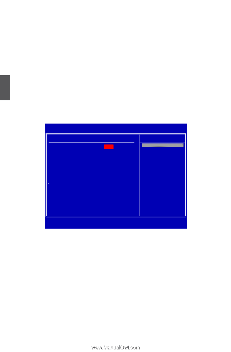
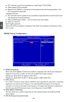
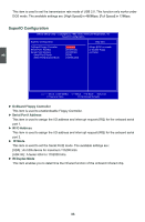
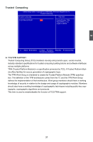
3 ■ DCT channels A and B can be ganged as a single logical 128-bit DIMM. ■ Offers highest DDR2 bandwidth. ■ Requires both DIMMs in a logical pair to have identical size and timing parameters, both DCTs programmed identically. Unganged channels ■ DCT channels A and B operate as two completely independent 64-bit channels (both chan- nels operate at the same frequency). ■ Reduce DRAM page conflicts - more concurrent open dram pages . ■ Better bus efficiency. Burst lengths supported When both DCTs are enabled in unganged mode, BIOS must initialize the frequency of each DCT in order. DRAM Timing Configuration CMOS Setup Utility - Copyright (C) 1985-2006, American Megatrends, Inc. DRAM Timing Configuration DRAM Timing Configuration Help Item DRAM Timing Mode [Auto Auto DCT 0 Options Move Enter:Select +/-/:Value F10:Save ESC:Exit F1:General Help F9:Optimized Defaults ► DRAM Timing Mode When both DCTs (DRAM controller) are enabled in unganged mode, BIOS must initialize the frequency of each DCT in order, you also can configure the timings manually. Settings are: [Auto], [DCT 0]. (appear in AM2 CPU) Settings are: [Auto], [DCT 0], [DCT 1], [Both]. (appear in AM2+/AM3 CPU) ► CAS Latency The number of memory clocks it takes a DRAM to return data after the read CAS_L is asserted depends on the memory clock frequency. The value that BIOS programs into the memory controller is a function of the target clock frequency. The target clock frequency is determined from the supported CAS latencies at given clock frequencies of each DIMM. ► TRCD (RAS-to-CAS Delay) This item allows you to select a delay time (in clock cycles) between the CAS# and RAS# strobe signals. ► TRP (Precharge Command Period) 32
-
 1
1 -
2
-
3
-
4
-
5
-
6
-
7
-
8
-
9
-
10
-
11
-
12
-
13
-
14
-
15
-
16
-
17
-
18
-
19
-
20
-
21
-
22
-
23
-
24
-
25
-
26
-
27
-
28
-
29
-
30
-
31
-
32
-
33
-
 34
34 -
 35
35 -
 36
36 -
 37
37 -
 38
38 -
 39
39 -
 40
40 -
 41
41 -
 42
42 -
 43
43 -
 44
44 -
45
-
46
-
47
-
48
-
49
-
50
-
51
-
52
-
53
-
54
-
55
-
56
-
57
-
58
-
59
-
60
-
61
-
62
-
63
-
64
-
65
-
66
-
67
-
68
-
69
-
70
-
71
-
72
-
73
-
74
-
75
-
76
-
77
-
78
-
79
-
80
-
81
-
82
-
83
-
84
-
85
-
86
-
87
-
88
-
89
-
90
-
91
-
92
-
93
-
94
-
95
-
96
-
97
-
98
-
99
-
100
-
101
-
102
-
103
-
104
 |
 |