Frigidaire FCRG3051BB Installation Instructions - Page 5
Anti-Tip Bracket Installation, Instructions
 |
View all Frigidaire FCRG3051BB manuals
Add to My Manuals
Save this manual to your list of manuals |
Page 5 highlights
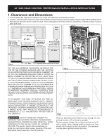
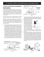
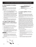
30" GAS REAR CONTROL FREESTANDING INSTALLATION INSTRUCTIONS 3. Anti-Tip Bracket Installation Instructions Important Safety Warning To reduce the risk of tipping of the range, the range should be secured to the floor by properly installed anti-tip bracket and screws packed with the range. Failure to install the anti-tip bracket will allow the range to tip over if excessive weight is placed on an open door or if a child climbs upon it. Serious injury might result from spilled hot liquids or from the range itself. If range is ever moved to a different location, the anti-tip brackets must also be moved and installed with the range. Instructions are provided for installation in wood or cement fastened to either the floor or wall. When installed to the wall, make sure that screws completely penetrate dry wall and are secured in wood or metal. When fastening to the floor or wall, be sure that screws do not penetrate electrical wiring or plumbing. A. Locate the Bracket Using the Template - (Bracket may be located on either the left or right side of the range. Use the information below to locate the bracket if template is not available). Mark the floor or wall where left or right side of the range will be located. If rear of range is against the wall or no further than 1-13/16" (45.6 mm) from wall when installed, you may use the wall or floor mount method. If molding is installed and does not allow the bracket to fit flush against the wall, remove molding or mount bracket to the floor. For wall mount, locate the bracket by placing the back edge of the template against the rear wall and the side edge of template on the mark made referencing the side of the range. Place bracket on top of template and mark location of the screw holes in wall. If rear of range is further than 1-13/16" (45.6 mm) from the wall when installed, attach bracket to the floor. More than 1-13/16" (45.6 mm) Fig. 5 For floor mount, locate the bracket by placing back edge of the template where the rear of the range will be located. Mark the location of the screw holes, shown in template. B. Drill Pilot Holes and Fasten Bracket - Drill a 1/8" (3 mm) pilot hole where screws are to be located. If bracket is to be mounted to the wall, drill pilot hole at an approximate 20° downward angle. If bracket is to be mounted to masonry or ceramic floors, drill a 3/16" (4.8 mm) pilot hole 1-3/4" (44 mm) deep. The screws provided may Fig. 6 be used in wood or concrete material. Use a 5/16" (8 mm) nut-driver or flat head screwdriver to secure the bracket in place. C. Level and Position Range - Level range by adjusting the (4) leveling legs with a wrench. Note: Aminimum clearance of 1/8" (3 mm) is required between the bottom of the range and the leveling leg to allow room for the bracket. Use a spirit level to check your adjustments. Slide range back into position. Visually check that rear leveling leg is inserted into and fully secured by the Anti-Tip Bracket by removing lower panel or storage drawer. For models with a warmer drawer or broiler compartment, grasp the top rear edge of the range and carefully attempt to tilt it forward. 1-13/16" Max. (45.6 mm) Fig. 4 Range Side or Cabinet Side (0", 0.5 mm) 5 Fig. 7
-
 1
1 -
 2
2 -
 3
3 -
 4
4 -
 5
5 -
 6
6 -
 7
7 -
 8
8 -
 9
9 -
 10
10 -
 11
11 -
12
-
13
-
14
-
15
-
16
-
17
-
18
-
19
-
20
-
21
-
22
-
23
-
24
-
25
-
26
-
27
-
28
-
29
-
30
-
31
-
32
 |
 |
