Frigidaire FH36DD50MS Use and Care Manual - Page 7
Plan the Ductwork, Plan the Discharge, CAUTION
 |
View all Frigidaire FH36DD50MS manuals
Add to My Manuals
Save this manual to your list of manuals |
Page 7 highlights
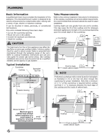
PLANNING Plan the Ductwork This downdraft blower system is designed for use with 3¼ x 10" ductwork (can be transitioned to 6" round). For best performance, choose the ducting option which allows the shortest length of ductwork and a minimum number of elbows and transitions. The system will operate most efficiently when the ductwork does not exceed 60 feet of equivalent duct. The downdraft will operate properly with ductwork up to 100 equivalent feet of duct. See page 12 for Calculated Duct Length Table. The blower can be mounted to the vent chassis housing to provide exhaust discharge down, as supplied (Fig. 1), or 90° to the left (Fig. 2) or 90° to the right (Fig. 3). Position the blower before installing the vent chassis housing in the countertop. NOTE For left or right discharge, the blower housing needs to be rotated for proper venting. See page 9 for instructions on rotating the blower. The blower is mounted on a slide plate which may be adjusted 3½" (8.9cm) left or right to help avoid duct interference with joists or other obstructions. To adjust the slide plate, loosen the 2 hex head (¼" driver) screws and move the slide plate to the desired position and tighten the screws. Plan the Discharge Fig. 2 - Discharge left Fig. 3 - Discharge right Use the 2 outermost screw holes for the blower slide plate. Hex Head Screw Inner Hole Slide Plate Adjustment Fig. 1 - Discharge down (as supplied) CAUTION To reduce risk of fire and to properly exhaust air, be sure to duct air outside - Do not vent exhaust air into spaces within walls or ceilings or into attics, crawl spaces, or garages. 7
-
 1
1 -
 2
2 -
 3
3 -
 4
4 -
 5
5 -
 6
6 -
 7
7 -
 8
8 -
 9
9 -
 10
10 -
 11
11 -
 12
12 -
13
-
14
-
15
-
16
 |
 |
