Frigidaire FH36DD50MS Use and Care Manual - Page 9
Installation
 |
View all Frigidaire FH36DD50MS manuals
Add to My Manuals
Save this manual to your list of manuals |
Page 9 highlights
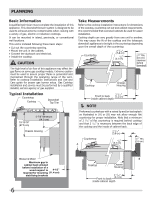
INSTALLATION 1. Cut Countertop Opening - Lay out and cut the cooktop cut-out far enough forward so downdraft will fit behind it (refer to cooktop installation instructions). - Set cooktop in place and slide it as far forward as possible. Center and square it with edges of countertop. A ½" minimum clearance behind cutout must be maintained for proper installation. Template - Place the template against the back flange of the cooktop and center it. Trace around template to mark the downdraft opening. - Remove cooktop from countertop. - Cut downdraft opening. Be careful not to chop edges of countertop. Mask the countertop to help prevent scratching the surface. - A ½" minimum clearance behind cutout must be maintained behind the telescopic downdraft for proper installation. NOTE Cabinet constructions may vary. Be sure to take cabinet frame members into account. They may have to be removed or relocated. Do not compromise the structural integrity of the cabinet in doing so. 2. Install Electrical Outlet - Mount a standard wiring box, with 3-pronged grounded receptacle, inside the cabinet. Make sure the downdraft's power cord can easily reach it. - Run appropriate power cable into cabinet and connect it to receptacle. 3. Prepare the Downdraft Blower System Duct Connection The downdraft is shipped with blower oriented for exhaust discharge down. Follow directions below to change to left or right exhaust discharge. Remove the blower and slide plate from the chassis housing by removing the two Phillips screws from the bottom slots and detaching the slide plate from the top tabs. Remove the four 1/4" nylon insert nuts from the blower studs and detach the slide plate. Rotate the blower 90 degrees left or right as required for ducting and reattach to the slide plate. Re-install the four 1/4" nylon insert nuts on the blower studs. Replace the blower and slide plate assembly by placing the slide plate underneath the top tabs and re-installing the two Hex Head screws in the bottom slots. Chassis Housing Top Tab 1/4" Nylon Insert Nuts Hex Head Screw (1 Each Side) Rotate Left or Right Slide Plate Blower 9
-
 1
1 -
2
-
3
-
 4
4 -
 5
5 -
 6
6 -
 7
7 -
 8
8 -
 9
9 -
 10
10 -
 11
11 -
 12
12 -
 13
13 -
 14
14 -
15
-
16
 |
 |
