Frigidaire FPGS3085KF Installation Instructions (All Languages) - Page 3
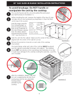
To avoid breakage: Do NOT handle or, manipulate the unit by the cooktop. - range
 |
UPC - 057112101538
View all Frigidaire FPGS3085KF manuals
Add to My Manuals
Save this manual to your list of manuals |
Page 3 highlights
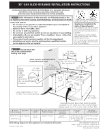
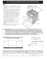
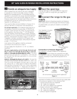
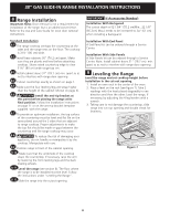
30" GAS SLIDE-IN RANGE INSTALLATION INSTRUCTIONS To avoid breakage: Do NOT handle or manipulate the unit by the cooktop. 1 The counter-top around the cut-out should be flat and leveled (see hatched area on illustration 1). Before installing the unit, measure the heights of the two (2) cabi- 2 net sides (H1-4), front and back (see illustration 1) from the floor to the top of the counter. Level the range using the four (4) leveling legs, so Shave Raised 1 ½" Max. (3.8 cm Max.) that the height from the Edge 3 floor to the underside of to Clear the metal flange is greater Space for a than the tallest cabinet 31½" (81 cm) measurement by at least Wide Cooktop. 1/16" (see illustration 2). H2 H1 H4 H3 4 Slide the unit into the cabinet. Make sure the center of the unit is aligned with the center of the cabinet cut-out. Remove the protective channels on each side of the cooktop 5 (if provided). The metal flange under each side of the cooktop MUST be placed over the cabinet countertop for proper unit support. The cooktop 6 should NOT rest directly on the countertop (see illustration 2) or else it could cause damage to the cooktop voiding the warranty. Level the unit if needed. Illustration 1 Metal Flange After the installation, MAKE SURE that 7 the unit is supported by the two front leveling legs and the two adjustable leveling wheels and NOT by the cooktop. To successfully install the range, the initial level height from floor to underside of cooktop frame should be at least 1/16" taller than cabinet sides as measured in step 2. Illustration 2 3
-
 1
1 -
 2
2 -
 3
3 -
 4
4 -
 5
5 -
 6
6 -
 7
7 -
 8
8 -
 9
9 -
10
-
11
-
12
-
13
-
14
-
15
-
16
-
17
-
18
-
19
-
20
-
21
-
22
-
23
-
24
-
25
-
26
-
27
-
28
-
29
-
30
-
31
-
32
-
33
-
34
-
35
-
36
 |
 |
