Frigidaire FPGS3085KF Installation Instructions (All Languages) - Page 9
Check Operation - lowes
 |
UPC - 057112101538
View all Frigidaire FPGS3085KF manuals
Add to My Manuals
Save this manual to your list of manuals |
Page 9 highlights
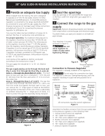
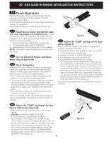
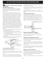
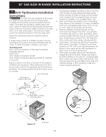
30" GAS SLIDE-IN RANGE INSTALLATION INSTRUCTIONS 10 Check Operation Refer to the Use and Care Guide packaged with the range for operating instructions and for care and cleaning of your range. Do not touch the elements or burners. They may be hot enough to cause burns. Remove all packaging from the oven before testing. 10.1 Install Burner Bases and Burner Caps This range is equipped with sealed burners It is very important to make sure that all of the Surface Burner Caps and Surface Burner Grates are installed correctly and at the correct locations. 1. Remove all packing material from cooktop area. 2. Discard all packing material (if applicable). 3. Unpack Burner Grates and position on the cooktop. NOTE: There are no burner adjustments necessary on this range. 10.2 Turn on Electrical Power and Open Main Shutoff Gas Valve 10.3 Check the Igniters Operation of electric igniters should be checked after range and supply line connectors have been carefully checked for leaks and range has been connected to electric power. To check for proper lighting: 1.Push in and turn a surface burner knob to the LITE position. You will hear the igniter sparking. 2. The surface burner should light when gas is available to the top burner. Each burner should light within four (4) seconds in normal operation after air has been purged from supply lines. Visually check that burner has lit. 3.Once the burner lights, the control knob should be rotated out of the LITE position. There are separate ignition devices for each burner. Try each knob separately until all burner valves have been checked. Figure 8 10.5 Adjust the "LOW" setting of the dual valve (Figure 9) Note: On the dual valve the low setting of each portion should be adjusted individually. a. Push in and turn control to LITE until the rear portion of the bridge burner ignites only. b. Quickly turn knob to LOWEST POSITION. c. If burner goes out, reset control to OFF. d. Remove the surface burner control knob. e. The rear portion of the bridge burner flame size can be increased or decreased with the turn of the screw A. Use screw B to adjust the flame size of the center portion of the bridge burner. Turn counterclockwise the screw to increase flame size. Turn clockwise the screw to decrease flame size. Adjust flame until you can quickly turn knob from LITE to LOWEST POSITION without extinguishing the flame. Flame should be as small as possible without going out. Note: Air mixture adjustment is not required on surface burners. 10.4 Adjust the "LOW" Setting of Surface Burner Valves (see Figure 8) a. Push in and turn each control to LITE until burner ignites. b.Quickly turn knob to LOWEST POSITION. c. If burner goes out, readjust valve as follows: Reset control to OFF. Remove the surface burner control knob, insert a thin-bladed screw driver into the hollow valve stem and engage the slotted screw inside. Flame size can be increased or decreased with the turn of the screw. Adjust flame until you can quickly turn knob from LITE to LOWEST POSITION without extinguishing the flame. Flame should be as small as possible without going out. 9 B A Figure 9
-
 1
1 -
2
-
3
-
 4
4 -
 5
5 -
 6
6 -
 7
7 -
 8
8 -
 9
9 -
 10
10 -
 11
11 -
 12
12 -
 13
13 -
 14
14 -
15
-
16
-
17
-
18
-
19
-
20
-
21
-
22
-
23
-
24
-
25
-
26
-
27
-
28
-
29
-
30
-
31
-
32
-
33
-
34
-
35
-
36
 |
 |
