Garmin GHP Compact Reactor Hydraulic Autopilot with GHC 20 Pack Installation I
Garmin GHP Compact Reactor Hydraulic Autopilot with GHC 20 Pack Manual
 |
View all Garmin GHP Compact Reactor Hydraulic Autopilot with GHC 20 Pack manuals
Add to My Manuals
Save this manual to your list of manuals |
Garmin GHP Compact Reactor Hydraulic Autopilot with GHC 20 Pack manual content summary:
- Garmin GHP Compact Reactor Hydraulic Autopilot with GHC 20 Pack | Installation I - Page 1
GHP™ Compact Reactor™ Hydraulic Installation Instructions Important Safety Information WARNING See the Important Safety and Product Information guide regain manual control of your boat. Learn to operate the autopilot on calm and hazard-free open water. Use caution when operating the autopilot near - Garmin GHP Compact Reactor Hydraulic Autopilot with GHC 20 Pack | Installation I - Page 2
The CCU is the primary sensor of the GHP Compact Reactor Hydraulic autopilot system. For best performance, observe these Pump Mounting Considerations Consult the hydraulic-layout diagrams in these instructions to help determine the pump-installation location (Hydraulic Layouts, page 4). • - Garmin GHP Compact Reactor Hydraulic Autopilot with GHC 20 Pack | Installation I - Page 3
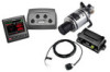
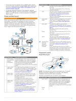
The helm control or compatible Garmin chartplotter and the CCU autopilot if necessary. Component Layout Single-Helm Layout NOTE: This diagram is for planning purposes only. If needed, specific connection diagrams are included in the detailed installation instructions for each component. Hydraulic - Garmin GHP Compact Reactor Hydraulic Autopilot with GHC 20 Pack | Installation I - Page 4
the steering system in your boat does not match any of the hydraulic layouts in this manual and you are unsure how to install the pump, contact Garmin Product Support. Before you start the pump installation, identify the type of hydraulic steering system in your boat. Each boat is different, and you - Garmin GHP Compact Reactor Hydraulic Autopilot with GHC 20 Pack | Installation I - Page 5
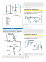
Dual-Helm without Power Assist Layout Return line à Helm Ä Power-assist module Å Shut-off valves Æ Pump Ç Steering cylinder È Single-Helm with Uflex® MasterDrive™ Layout CAUTION When installing the pump in a system with a Uflex MasterDrive, do not cut the high-pressure line connecting the power - Garmin GHP Compact Reactor Hydraulic Autopilot with GHC 20 Pack | Installation I - Page 6
helm control is not included in all autopilot packages. If you install the autopilot without a dedicated helm control, the autopilot CCU must be connected to the same NMEA 2000 network as a compatible Garmin chartplotter to configure and control the autopilot system. You must install the helm - Garmin GHP Compact Reactor Hydraulic Autopilot with GHC 20 Pack | Installation I - Page 7
autopilot components hydraulic line that connects directly to the pump. Bleeding the Hydraulics NOTICE This is a general procedure for bleeding a hydraulic steering system. Refer to the instructions Manually steer the helm fully to port. 4 Open both bypass valves at the cylinder fittings. 5 Manually - Garmin GHP Compact Reactor Hydraulic Autopilot with GHC 20 Pack | Installation I - Page 8
should be applied to the pump after all hydraulic and electrical connections are made and the hydraulic system has been bled. Connecting the CCU Route document, select Manuals on the product page for your device at www.garmin.com. Building a Basic NMEA 2000 Network for the Autopilot System NOTICE - Garmin GHP Compact Reactor Hydraulic Autopilot with GHC 20 Pack | Installation I - Page 9
compatible Garmin chartplotter to configure the autopilot. See the included configuration guide for more information on configuring the autopilot. autopilot system must be connected to a compatible Garmin chartplotter on the same NMEA 2000 network as the CCU. See the installation instructions - Garmin GHP Compact Reactor Hydraulic Autopilot with GHC 20 Pack | Installation I - Page 10
• The internal NMEA 0183 ports and communication protocols are configured on the connected Garmin device. See the NMEA 0183 section of the chartplotter owner's manual for more information. • The ground wires on the NMEA 0183 data cable and your NMEA 0183 device must both be connected to ground. • - Garmin GHP Compact Reactor Hydraulic Autopilot with GHC 20 Pack | Installation I - Page 11
Specifications Compact Pump Specification Dimensions (H × W × D) Weight Temperature 1 m for up to 30 min. For more information, go to www.garmin.com/waterrating. Helm Control Specification Measurement Dimensions without sun cover (H 110 x devices, the autopilot uses the following NMEA 0183 - Garmin GHP Compact Reactor Hydraulic Autopilot with GHC 20 Pack | Installation I - Page 12
Autopilot support information. • In the USA, call 913-397-8200 or 1-800-800-1020. • In the UK, call 0808 238 0000. • In Europe, call +44 (0) 870 850 1241. Garmin® and the Garmin logo are trademarks of Garmin Ltd. or its subsidiaries, registered in the USA and other countries. GHP™, GHC™, Reactor
-
 1
1 -
 2
2 -
 3
3 -
 4
4 -
 5
5 -
 6
6 -
 7
7 -
8
-
9
-
10
-
11
-
12
 |
 |
GHP
™
Compact
Reactor
™
Hydraulic
Installation Instructions
Important Safety Information
WARNING
See the
Important Safety and Product Information
guide in the
product box for product warnings and other important
information.
You are responsible for the safe and prudent operation of your
vessel. The autopilot is a tool that enhances your capability to
operate your boat. It does not relieve you of the responsibility of
safely operating your boat. Avoid navigational hazards and
never leave the helm unattended.
Always be prepared to promptly regain manual control of your
boat.
Learn to operate the autopilot on calm and hazard-free open
water.
Use caution when operating the autopilot near hazards in the
water, such as docks, pilings, and other boats.
CAUTION
When in use, beware of hot motor and solenoid components
and the risk of entrapment from moving parts.
Failure to install and maintain this equipment in accordance with
these instructions could result in damage or injury.
NOTICE
To avoid damage to your boat, the autopilot system should be
installed by a qualified marine installer. Specific knowledge of
hydraulic steering componentry and marine electrical systems is
required for proper installation.
Installation Preparation
The autopilot system consists of multiple components. You
should familiarize yourself with all of the component mounting
and connection considerations before beginning installation. You
must know how the components operate together in order to
correctly plan the installation on your boat.
You can consult the layout diagrams (
Power and Data Layout
,
page 3
) to help understand the mounting and connection
considerations.
You should lay out all of the components on the boat as you
plan the installation to make sure your cables will reach each
component. If needed, extension cables (sold separately) for
various components are available from your Garmin
®
dealer or
from
www.garmin.com
.
You should record the serial number of each component for
registration and warranty purposes.
Tools Needed
•
Safety glasses
•
Drill and drill bits
•
Wrenches
•
90 mm (3.5 in.) hole saw or a rotary cutting tool (for installing
an optional helm control)
•
Wire cutters/strippers
•
Phillips and flat screwdrivers
•
Cable ties
•
Single Pole Single Throw (SPST) switch (to use as an
autopilot bypass when not installing the Shadow Drive
™
valve)
•
Waterproof wire connectors (wire nuts) or heat-shrink tubing
and a heat gun
•
Marine sealant
•
Marine corrosion inhibitor spray
•
Portable or handheld compass (to test for magnetic
interference)
•
Hydraulic hose with machine-crimped or field-replaceable
fittings that have a minimum rating of 1000 lbf/in
2
•
Hydraulic T-fittings
•
Inline hydraulic shut-off valves
•
Hydraulic fluid
•
Thread sealant
•
Hydraulic bleeding equipment
•
Anti-seize lubricant (optional)
NOTE:
Mounting screws are provided for the main components
of the autopilot system. If the provided screws are not
appropriate for the mounting surface, you must provide the
correct types of screws.
Mounting and Connection Considerations
The autopilot components connect to each other and to power
using the included cables. Ensure that the correct cables reach
each component and that each component is in an acceptable
location before mounting or wiring any components.
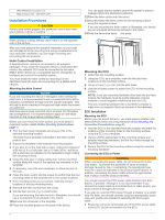
Helm Control Mounting Considerations
A dedicated helm control is not included in all autopilot
packages. If you install the autopilot without a dedicated helm
control, the autopilot CCU must be connected to the same
NMEA 2000
®
network as a compatible Garmin chartplotter to
configure and control the autopilot system.
NOTICE
This device should be mounted in a location that is not exposed
to extreme temperatures or conditions. The temperature range
for this device is listed in the product specifications. Extended
exposure to temperatures exceeding the specified temperature
range, in storage or operating conditions, may cause device
failure. Extreme-temperature-induced damage and related
consequences are not covered by the warranty.
The mounting surface must be flat to avoid damaging the device
when it is mounted.
Using the included hardware and template, you can flush mount
the helm control in the dashboard. When selecting a mounting
location, observe these considerations.
•
The mounting location should be at or below eye level to
provide optimal viewing as you operate your vessel.
•
The mounting location should allow easy access to the keys
on the device.
•
The mounting surface must be strong enough to support the
weight of the device and protect it from excessive vibration or
shock.
January 2016
Printed in Taiwan
190-01831-02_0A