Garmin GHP Compact Reactor Hydraulic Autopilot with GHC 20 Pack Installation I - Page 7
Pump Installation
 |
View all Garmin GHP Compact Reactor Hydraulic Autopilot with GHC 20 Pack manuals
Add to My Manuals
Save this manual to your list of manuals |
Page 7 highlights
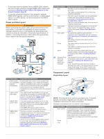
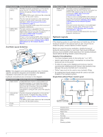
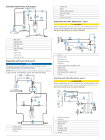
2 Route the bare-wire end of the ECU power cable to the boat battery. If the wire is not long enough, it can be extended (Power Cable Extensions, page 7). 3 Connect the black wire (-) to the negative (-) terminal of the battery, and connect the red wire (+) to the positive (+) terminal of the battery. 4 After you install all of the other autopilot components, connect the power cable to the ECU. Power Cable Extensions If necessary, the power cable can be extended using the appropriate wire gauge for the length of the extension. Item À Á Â Description Fuse Battery 9 ft. (2.7 m) no extension Item Description Splice 10 AWG (5.26 mm²) extension wire Fuse 8 in. (20.3 cm) Battery 8 in. (20.3 cm) Up to 15 ft. (4.6 m) Item Description Splice 8 AWG (8.36 mm²) extension wire Fuse 8 in. (20.3 cm) Battery 8 in. (20.3 cm) Up to 23 ft. (7 m) Item Description Splice 6 AWG ( 13.29 mm²) extension wire Fuse 8 in. (20.3 cm) Battery 8 in. (20.3 cm) Up to 36 ft. (11 m) Pump Installation Mounting the Pump Before you can mount the pump, you must select a location (Pump Mounting Considerations, page 2) and determine the correct mounting hardware (Tools Needed, page 1). 1 Hold the pump in the intended mounting location and mark the locations of the mounting holes on the mounting surface, using the pump as a template. 2 Using a drill bit appropriate for the mounting surface and selected mounting hardware, drill the four holes through the mounting surface. 3 Secure the pump to the mounting surface using the selected mounting hardware. Connecting the Hydraulic Lines to the Pump Refer to the layout diagrams for assistance (Hydraulic Layouts, page 4). 1 Disconnect the necessary lines from the hydraulic system. 2 Add a T-connector to the starboard and port lines of the system between the helm and the steering cylinder. NOTE: If the boat has a power-assist module, you must add the T-connectors between the power-assist module and the steering cylinder. 3 Complete an action: • If the boat does not have a power-assist module, add enough hydraulic hose to connect the return fitting on the helm to the center pump fitting. • If the boat has a power-assist module, add a T-connector to the return line of the system between the power-assist module and the helm. A return line should already exist between the helm and the power-assist module. 4 Add hydraulic hose to the unused fitting on each T-connector, with enough hose to connect the T-connector to the pump fittings. 5 Connect the port and starboard line T-connectors to the appropriate pump fittings, as shown in the layout diagram for your hydraulic configuration. 6 Install the Shadow Drive in the port or starboard hydraulic line between the helm and the T-connector (Installing the Shadow Drive, page 8). 7 Install a shut-off valve (not included) on each hydraulic line that connects directly to the pump. Bleeding the Hydraulics NOTICE This is a general procedure for bleeding a hydraulic steering system. Refer to the instructions provided by the manufacturer of the steering system for more-specific information about bleeding the system. Before you bleed the hydraulic system, you should verify that all hose connections are complete and fully tightened. 1 Select an option: • If the helm reservoir contains insufficient fluid, fill it as needed. • If the helm reservoir contains excess fluid, remove the excess to avoid fluid overflow during the bleeding process. 2 Insert a bypass hose between the cylinder bleed ports. TIP: If you use a clear plastic hose for this bypass, you can observe air bubbles during the bleeding processes. 3 Manually steer the helm fully to port. 4 Open both bypass valves at the cylinder fittings. 5 Manually turn the helm slowly to port over three minutes. TIP: You can stop turning when you no longer see air moving through the bypass hose. 7
-
 1
1 -
 2
2 -
 3
3 -
 4
4 -
 5
5 -
 6
6 -
 7
7 -
 8
8 -
 9
9 -
 10
10 -
 11
11 -
 12
12
 |
 |
