Garmin GHP Compact Reactor Hydraulic Autopilot with GHC 20 Pack Installation I - Page 8
Connecting the CCU, Installing the Shadow Drive, Installing an Autopilot Switch, Installing
 |
View all Garmin GHP Compact Reactor Hydraulic Autopilot with GHC 20 Pack manuals
Add to My Manuals
Save this manual to your list of manuals |
Page 8 highlights
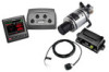
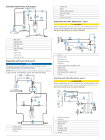
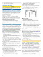
6 Turn on the autopilot system and disable the Shadow Drive. You can refer to the autopilot system documentation for more information on disabling the Shadow Drive. 7 Hold (port) on the helm control for at least 10 seconds. TIP: You can stop holding when you no longer see air moving through the bypass hose. 8 Close both bypass valves at the cylinder fittings. 9 If necessary, add fluid to the helm reservoir. 10Repeat steps 3 through 9 for the starboard side. 11Hold (port) on the helm control until steering stops and Hydraulic Pump Stall is shown on the helm control. 12Hold (starboard) on the helm control until steering stops and Hydraulic Pump Stall is shown on the helm control. 13Select an option: • If Hydraulic Pump Stall is not shown within 2 to 3 seconds after the cylinder stops, repeat steps 1-13 to bleed the system again. • If Hydraulic Pump Stall is shown within 2 to 3 seconds after the cylinder stops, the system bleed completed successfully. After hydraulic bleeding is complete, you can re-enable the Shadow Drive. Corrosion Blocker NOTICE To ensure the long life of all parts, apply corrosion blocker to the pump at least twice yearly. A marine-rated corrosion blocker should be applied to the pump after all hydraulic and electrical connections are made and the hydraulic system has been bled. Connecting the CCU Route the orange and blue wires from the bare-wire portion of the CCU cable to the location where you plan to install the alarm (Installing the Alarm, page 8). If the cable is not long enough, extend the appropriate wires with 0.08 mm2 (28 AWG) wire. Installing the Shadow Drive Connecting the Shadow Drive to the Hydraulic System Before you can install the Shadow Drive, you must select a location at which to connect the Shadow Drive to the hydraulic steering of your boat (Shadow Drive Mounting Considerations, page 2). For further assistance, consult the hydraulic-layout diagrams (Hydraulic Layouts, page 4). Use hydraulic connectors (not included) to install the Shadow Drive in the appropriate hydraulic line. Connecting the Shadow Drive to the CCU 1 Route the bare-wire end of the CCU cable to the Shadow Drive. If the cable is not long enough, extend the appropriate wires with 28 AWG (0.08 mm²) wire. 2 Connect the cables, based on this table. Shadow Drive Wire Color CCU Cable Wire Color Red (+) Brown (+) Black (-) Black (-) 3 Solder and cover all bare-wire connections. Installing an Autopilot Switch If your autopilot package does not include a Shadow Drive valve, you should install a manual Single Pole Single Throw (SPST) switch (not included) to disable the autopilot if necessary. 8 1 Route the bare-wire end of the CCU cable to the switch. If the cable is not long enough, extend the appropriate wires with 28 AWG (0.08 mm²) wire. 2 Connect the cables, based on this table. Switch Wire Function CCU Cable Wire Color Positive (+) Brown (+) Negative (-) Black (-) 3 Solder and cover all bare-wire connections. The autopilot functions correctly when the switch contacts are closed. Opening the switch disables the autopilot for manual steering. Installing the Alarm Before you can mount the alarm, you must select a mounting location (Alarm Mounting and Connection Considerations, page 2). 1 Route the alarm cable to the bare-wire end of the CCU cable. If the cable is not long enough, extend the appropriate wires with 28 AWG (0.08 mm2) wire. 2 Connect the cables, based on this table. Alarm Wire Color CCU Cable Wire Color White (+) Orange (+) Black (-) Blue (-) 3 Solder and cover all bare-wire connections. 4 Secure the alarm with cable ties or other mounting hardware (not included). NMEA 2000 and the Autopilot Components A dedicated helm control is not included in all autopilot packages. If you install the autopilot without a dedicated helm control, the autopilot CCU must be connected to the same NMEA 2000 network as a compatible Garmin chartplotter to configure and control the autopilot system. NOTICE If you have an existing NMEA 2000 network on your boat, it should already be connected to power. Do not connect the NMEA 2000 power cable to an existing NMEA 2000 network, because only one power source should be connected to a NMEA 2000 network. You can connect the CCU and the optional helm control through an existing NMEA 2000 network. If you do not have an existing NMEA 2000 network on your boat, all the parts needed to build one are supplied in the autopilot package (Building a Basic NMEA 2000 Network for the Autopilot System, page 8). To use the advanced features of the autopilot, optional NMEA 2000 devices, such as a GPS device, can be connected to the NMEA 2000 network. If you are unfamiliar with NMEA 2000, you should read the "NMEA 2000 Network Fundamentals" chapter of the Technical Reference for NMEA 2000 Products. To download this document, select Manuals on the product page for your device at www.garmin.com. Building a Basic NMEA 2000 Network for the Autopilot System NOTICE If you are installing a NMEA 2000 power cable, you must connect it to the boat ignition switch or through another in-line switch. NMEA 2000 devices will drain your battery if the NMEA 2000 power cable is connected to the battery directly. A dedicated helm control is not included in all autopilot packages. If you install the autopilot without a dedicated helm control, the autopilot CCU must be connected to the same NMEA 2000 network as a compatible Garmin chartplotter to configure and control the autopilot system.
-
 1
1 -
2
-
 3
3 -
 4
4 -
 5
5 -
 6
6 -
 7
7 -
 8
8 -
 9
9 -
 10
10 -
 11
11 -
 12
12
 |
 |
