Garmin GHP Compact Reactor Hydraulic Autopilot with GHC 20 Pack Installation I - Page 6
Installation Procedures
 |
View all Garmin GHP Compact Reactor Hydraulic Autopilot with GHC 20 Pack manuals
Add to My Manuals
Save this manual to your list of manuals |
Page 6 highlights
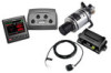
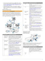
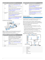
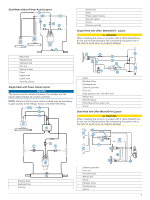
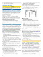
Uflex MasterDrive power unit È High pressure line - DO NOT CUT É Installation Procedures CAUTION Always wear safety goggles, ear protection, and a dust mask when drilling, cutting, or sanding. NOTICE When drilling or cutting, always check what is on the opposite side of the surface. After you have planned the autopilot installation on your boat and satisfied all of the mounting and wiring considerations for your particular installation, you can begin mounting and connecting the components. Helm Control Installation A dedicated helm control is not included in all autopilot packages. If you install the autopilot without a dedicated helm control, the autopilot CCU must be connected to the same NMEA 2000 network as a compatible Garmin chartplotter to configure and control the autopilot system. You must install the helm control by mounting it in the dashboard near the helm and connecting it to a NMEA 2000 network. Mounting the Helm Control NOTICE If you are mounting the device in fiberglass, when drilling the pilot holes, it is recommended to use a countersink bit to drill a clearance counterbore through only the top gel-coat layer. This will help to avoid cracking in the gel-coat layer when the screws are tightened. Stainless-steel screws may bind when screwed into fiberglass and overtightened. It is recommended to apply an anti-seize lubricant on the screws before installing them. Before you can mount the helm control, you must select a mounting location (Helm Control Mounting Considerations, page 1). 1 Trim the flush-mount template and ensure it fits in the selected mounting location. The flush-mount template is included in the helm control product box. 2 Secure the template to the selected mounting location. 3 If you plan to cut the hole with a rotary cutting tool instead of a 90 mm (3.5 in.) hole saw, use a 10 mm (3/8 in.) drill bit to drill a pilot hole as indicated on the template to begin cutting the mounting surface. 4 Using the hole saw or rotary cutting tool, cut the mounting surface along the inside of the dashed line indicated on the template. 5 If necessary, use a file and sandpaper to refine the size of the hole. 6 Place the helm control into the cutout to confirm that the four mounting holes on the template are in the correct locations. 7 If the mounting holes are not correct, mark the correct locations of the four mounting holes. 8 Remove the helm control from the cutout. 9 Drill the four 2.8 mm (7/64 in.) pilot holes. If you are mounting the helm control in fiberglass, you should use a countersink bit as advised in the notice. 10Remove the remainder of the template. 11Place the included gasket on the back of the device. You can apply marine sealant around the gasket to prevent leakage behind the dashboard (optional). 12Place the helm control into the cutout. 13Securely fasten the helm control to the mounting surface using the supplied screws. If you are mounting the helm control in fiberglass, you should use an anti-seize lubricant as advised in the notice. 14Snap the decorative bezel into place. À Mounting the CCU 1 Determine the mounting location. 2 Using the CCU as a template, mark the two pilot hole locations on the mounting surface. 3 Using a 3 mm (1/8 in.) bit, drill the pilot holes. 4 Use the included screws to attach the CCU to the mounting surface. NOTE: If you use mounting hardware other than the provided screws, the hardware must be quality stainless or brass material to avoid magnetic interference with the CCU. Test any mounting hardware with a handheld compass to make sure no magnetic fields are present in the hardware. ECU Installation Mounting the ECU Before you can mount the ECU, you must select a location and determine the correct mounting hardware (ECU Mounting and Connection Considerations, page 2). 1 Hold the ECU in the intended mounting location and mark the locations of the mounting holes on the mounting surface, using the ECU as a template. 2 Using a drill bit appropriate for the mounting surface and selected mounting hardware, drill the four holes through the mounting surface. 3 Secure the ECU to the mounting surface using the selected mounting hardware. Connecting the ECU to Power WARNING When connecting the power cable, do not remove the in-line fuse holder. To prevent the possibility of injury or product damage caused by fire or overheating, the appropriate fuse must be in place as indicated in the product specifications. In addition, connecting the power cable without the appropriate fuse in place voids the product warranty. You should connect the ECU power cable directly to the boat battery, if possible. Although it is not recommended, if you connect the power cable to a terminal block or other source, you must connect it through a 40 A fuse. If you plan to route the ECU power through a breaker or a switch near the helm, you should consider using an appropriately sized relay and control wire instead of extending the ECU power cable. 1 Route the connector-terminated end of the ECU power cable to the ECU, but do not connect it to the ECU. 6
-
 1
1 -
 2
2 -
 3
3 -
 4
4 -
 5
5 -
 6
6 -
 7
7 -
 8
8 -
 9
9 -
 10
10 -
 11
11 -
 12
12
 |
 |
