Gateway ML6714 8511725 - Gateway Service Guide - Page 62
Replace the keyboard by following the instructions - hard drive
 |
View all Gateway ML6714 manuals
Add to My Manuals
Save this manual to your list of manuals |
Page 62 highlights
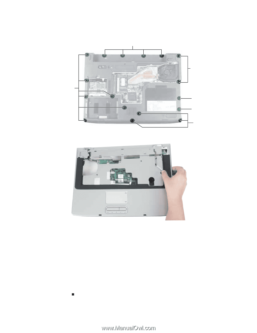
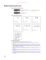
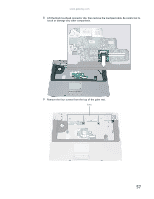
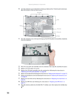
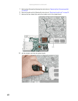
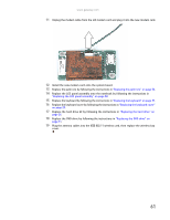
Replacing Notebook Components 10 Turn the notebook over so the bottom is facing up. Remove the 17 bottom palm rest screws. Note the location of the six short screws. Short screws Screws Screws Short screw Short screw Screws 11 Turn the notebook over so the top is facing up, then lift the palm rest assembly completely from the notebook. 12 Place the new palm rest assembly onto the notebook, then snap the assembly into place. 13 Replace all of the palm rest screws. 14 Replace the LCD panel assembly onto the notebook by following the instructions in "Replacing the LCD panel assembly" on page 38. 15 Replace the keyboard by following the instructions in "Replacing the keyboard" on page 31. 16 Replace the keyboard cover by following the instructions in "Replacing the keyboard cover" on page 29. 17 Replace the hard drive kit by following the instructions in "Replacing the hard drive" on page 26. 18 Replace the DVD drive by following the instructions in "Replacing the DVD drive" on page 11. 19 Plug the antenna cables into the IEEE 802.11 wireless card, then replace the wireless bay cover. 58
-
 1
1 -
2
-
3
-
4
-
5
-
6
-
7
-
8
-
9
-
10
-
11
-
12
-
13
-
14
-
15
-
16
-
17
-
18
-
19
-
20
-
21
-
22
-
23
-
24
-
25
-
26
-
27
-
28
-
29
-
30
-
31
-
32
-
33
-
34
-
35
-
36
-
37
-
38
-
39
-
40
-
41
-
42
-
43
-
44
-
45
-
46
-
47
-
48
-
49
-
50
-
51
-
52
-
53
-
54
-
55
-
56
-
 57
57 -
 58
58 -
 59
59 -
 60
60 -
 61
61 -
 62
62 -
 63
63 -
 64
64 -
 65
65 -
 66
66 -
 67
67 -
68
-
69
-
70
-
71
-
72
-
73
-
74
-
75
-
76
-
77
-
78
 |
 |