GE 27958GE1 User Guide - Page 10
Allow the handset to charge for 12 hours prior to first use. If you don't, properly charge - battery
 |
UPC - 044319202373
View all GE 27958GE1 manuals
Add to My Manuals
Save this manual to your list of manuals |
Page 10 highlights
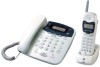
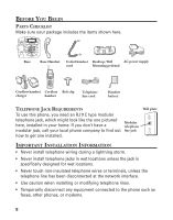
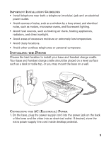
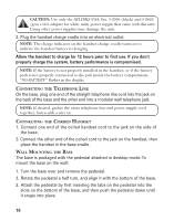
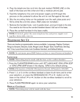
CAUTION: Use only the ATLINKS USA, Inc. 5-2596 (black) and 5-2625 (gray color adapter for white unit) power supply that came with this unit. Using other power supplies may damage the unit. 2. Plug the handset charge cradle into an electrical outlet. NOTE: The charge indicator on the handset charge cradle turns on to indicate the handset battery is charging Allow the handset to charge for 12 hours prior to first use. If you don't properly charge the system, battery performance is compromised. NOTE: If the battery is not properly installed in the handset, or if the battery pack is not properly connected to the jack inside the battery compartment, "NO BATTERY " flashes in the display. CONNECTING THE TELEPHONE LINE On the base, plug one end of the straight telephone line cord into the jack on the back of the base and the other end into a modular wall telephone jack. NOTE: If desired, gather the extra telephone line and power supply cord together, fasten with a wire tie. CONNECTING THE CORDED HANDSET 1. Connect one end of the coiled handset cord to the jack on the side of the base. 2. Connect the other end of the coiled cord to the jack on the handset, then place the handset in the base cradle. WALL MOUNTING THE BASE The base is packaged with the pedestal attached in desktop mode. To mount the base on the wall: 1. Turn the base over and remove the pedestal. 2. Rotate the pedestal a half turn, and align it with the bottom of the base. 3. Attach the pedestal by first inserting the tabs on the pedestal into the slots on the bottom of the base, and then push the pedestal down until it snaps into place. 10
-
 1
1 -
2
-
3
-
4
-
 5
5 -
 6
6 -
 7
7 -
 8
8 -
 9
9 -
 10
10 -
 11
11 -
 12
12 -
 13
13 -
 14
14 -
 15
15 -
16
-
17
-
18
-
19
-
20
-
21
-
22
-
23
-
24
-
25
-
26
-
27
-
28
-
29
-
30
-
31
-
32
-
33
-
34
-
35
-
36
-
37
-
38
-
39
-
40
-
41
-
42
-
43
-
44
-
45
-
46
-
47
-
48
-
49
-
50
-
51
-
52
-
53
-
54
-
55
-
56
-
57
-
58
-
59
-
60
-
61
-
62
-
63
-
64
-
65
-
66
-
67
-
68
-
69
-
70
-
71
-
72
-
73
-
74
-
75
-
76
-
77
-
78
-
79
-
80
-
81
-
82
-
83
-
84
-
85
-
86
-
87
-
88
-
89
-
90
-
91
-
92
-
93
-
94
-
95
-
96
 |
 |
