GE JX827BN Installation Instructions
GE JX827BN - Trim Kit For 1.0 cu. Ft. Microwave Ovens Manual
 |
View all GE JX827BN manuals
Add to My Manuals
Save this manual to your list of manuals |
GE JX827BN manual content summary:
- GE JX827BN | Installation Instructions - Page 1
Microwave Oven Installation instructions for your new Built-In Trim Kit JX827BN, JX827WN, JX827SS, JX827CD CAUTION: • Before you begin-Read these instructions, Owner's Manual and Important Safety Instructions completely and carefully. • This Kit is for use on models: JEM21K/L, JEM23K/L, JEM25L/GN - GE JX827BN | Installation Instructions - Page 2
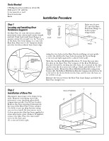
Step 1 Locating and Installing Rear Holddown Supports Set Base Pan (1) into the front cabinet microwave oven cutout and center it right and left. Power Outlet using the two holes in the Base Pan front flange as your guide (center the drill in the base holes keeping the front flange centered and - GE JX827BN | Installation Instructions - Page 3
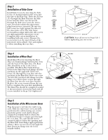
the Side Cover bottom. Drive two Screws (E) through the Side Cover into the microwave oven holes where the microwave plug buttons were removed. Be sure the side covers are tight against the sides of the microwave oven (the trim frame screws will not align unless the side covers are tight against the - GE JX827BN | Installation Instructions - Page 4
with Top Trim (4). Screw D Side Trim (6) Screw D Top Trim (4) Bottom Trim (5) Screw D Screw D Side Trim (6) Screw D Step 7 Installing the Trim Kit Frame 1. Using the assembled Trim Kit Frame as a template (and with the microwave oven in position and secured), insert the Trim Kit Frame into
-
 1
1 -
 2
2 -
 3
3 -
 4
4
 |
 |
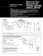
Installation instructions
for your new
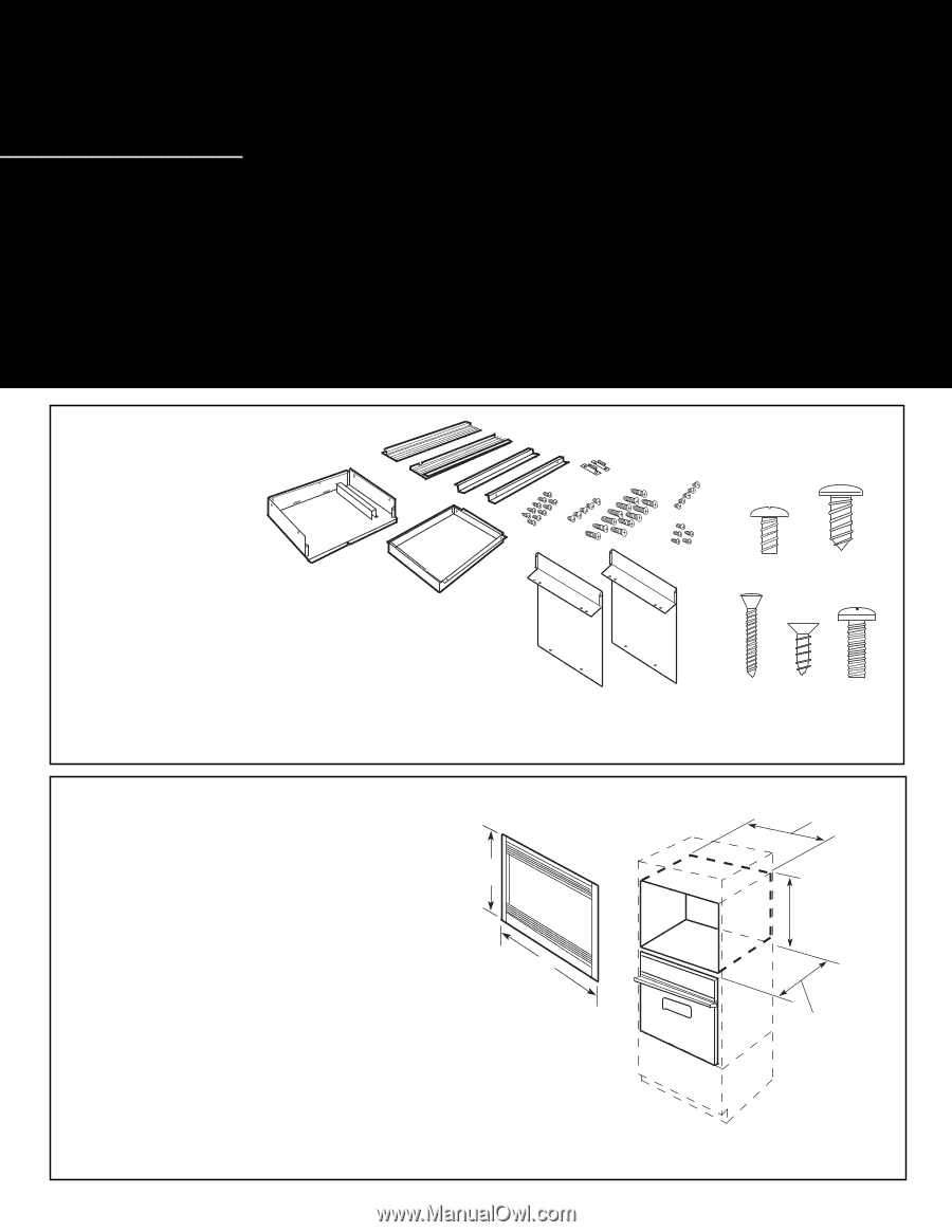
Parts List
1. Base Pan
2. Rear Duct
3. Side Covers (2)
4. Top Trim
5. Bottom Trim
6. Side Trims
7. Rear Holddown Brackets
Screws
A
(9 required 1 extra)
B
(4 required 1 extra)
C
(10 required 2 extra)
D (4 required 1 extra)
E
(4 required 1 extra)
Note:
This kit has extra screws to prevent technician from spending extra time locating a replacement in case
they lose one during installation.
Cabinet Cutout Dimensions and Specifications
Allow 1-1/4" for overlap of the Microwave Oven Kit
Trim over all the edges of the cutout for the
Microwave Oven Kit.
WIDTH
HEIGHT
24-7/8"
±
1/16"
15"
±
1/16"
DEPTH
16" Min. receptacle outside cutout
18" Min. receptacle inside cutout
120 volt—60 Hertz grounded power receptacle.
For Installation Above a Built-In Oven
Microwave oven should be installed on a
3/8" plywood base and supported by 2x4 or
1x2 equivalent runners on all sides. Base
must be capable of supporting a minimum
of 100 lbs.
Screw E
Screw D
1
Parts Inventory
B
2
4
5
6
C
A
E
D
7
3
3
Screw C
Screw A
Screw B
CAUTION:
•
Before you begin—Read these instructions, Owner’s Manual and Important Safety Instructions
completely and carefully.
•
This Kit is for use on models: JEM21K/L, JEM23K/L, JEM25L/GN/GV/GY/WN/WV/WY/BF/WF, JES833WY,
JEM825K, JEM27KWH/LWH, JEM31L/M/GN/GV/GY/WV/WY/GA/WA/CA/BF/CF/WF/SF, JEM33L/M, JEM34M
and ZEM200WN/WV/WY/GV/GY/SY/GW/WA/SA/GA/SF/BF/WF.
•
This kit can be installed alone or over any General Electric/Hotpoint/RCA single electric wall oven.
•
Do not alter or modify any part of this kit or the oven.
•
Observe all governing codes and ordinances.
•
Oven must be plugged into a properly grounded 3-hole, 120 volt receptacle as required by the
National Electrical Code.
•
Unplug the microwave oven before attempting installation of this kit.
•
Save these instructions (for Local Inspectors and Future Reference).
18" Min.
receptacle
in cabinet
16" Min.
receptacle
outside
cabinet
24-7
∕
8"
±
1
∕
16"
15"
±
1
∕
16"
TRIM
STRIPS
16-1/4"
26-1/8"
Microwave Oven
Built-In Trim Kit
JX827BN, JX827WN,
JX827SS, JX827CD