GE JX827BN Installation Instructions - Page 4
Step 7, Installing the Trim Kit Frame, Step 6, Assembling the Trim Kit Frame - parts
 |
View all GE JX827BN manuals
Add to My Manuals
Save this manual to your list of manuals |
Page 4 highlights
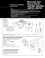
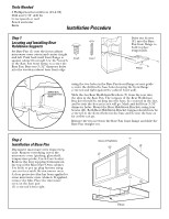
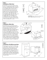
Step 6 Assembling the Trim Kit Frame Assemble Top Trim (4), Bottom Trim (5) and Side Trims (6) shown with the #6 x 1/2"L flat head thread-forming screws (D). Fasten through holes in the Trim Kit Sides (6) as shown. CAUTION: After assembly, top, bottom and side strips must be flush. Note: Bottom Trim (5) has a hinge notch and is not interchangeable with Top Trim (4). Screw D Side Trim (6) Screw D Top Trim (4) Bottom Trim (5) Screw D Screw D Side Trim (6) Screw D Step 7 Installing the Trim Kit Frame 1. Using the assembled Trim Kit Frame as a template (and with the microwave oven in position and secured), insert the Trim Kit Frame into the cutout and locate the attaching holes. Temporarily hold the Trim Kit Frame in place by starting the four screws that attach the trim kit frame to the Base Pan and Side Covers. Push the Trim Kit Frame as far to the left as possible driving the four inside screws into Base Pan and Side Cover. Be sure the door clears the trim when open. Mark the four holes on the side trim. 2. Remove the Trim Kit Frame. 3. Center punch and drill 3/32" dia. pilot holes per their hole center marks for the mounting screws. 4. Position the assembled Trim Kit Frame around the Oven and secure it with 8 screws (C). Use the smaller Phillips head screwdriver (#1) to prevent burring the Phillips head. Mark Mark Trim Kit Frame Mark Mark Wall Installation CAUTION: Do not overtighten screws since it can cause misalignment of top/ side strips. Screw C Part No. 245B1790P064 (2) Pub. No. 31-1163 (2) SPECIFICATIONS SUBJECT TO CHANGE WITHOUT NOTICE (N.D. 558) 7/02
-
 1
1 -
 2
2 -
 3
3 -
 4
4
 |
 |
