GE JX827BN Installation Instructions - Page 3
Step 3, Installation of Side Cover, Step 4, Installation of Rear Duct, Step 5, Installation of
 |
View all GE JX827BN manuals
Add to My Manuals
Save this manual to your list of manuals |
Page 3 highlights
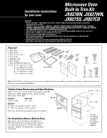
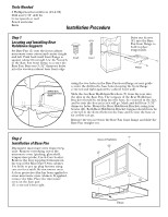
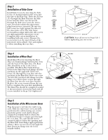
Step 3 Installation of Side Cover Install Side Covers by inserting the Side Cover (3) bottom between the oven and the side of the Base Pan. Drive two Screws (A) through the Base Pan into the Side Cover bottom. Drive two Screws (E) through the Side Cover into the microwave oven holes where the microwave plug buttons were removed. Be sure the side covers are tight against the sides of the microwave oven (the trim frame screws will not align unless the side covers are tight against the microwave oven). Complete side covers installation by installing both side covers. Remove the screw located on the top left back of the microwave oven cabinet. Save and replace it when installing the rear duct. Screws E Screw A Screw E SARVEEMSOCVREE&W Screws A CAUTION: Start all screws in Steps 3 & 4 before tightening any one screw. Step 4 Installation of Rear Duct Install Rear Duct by inserting the Rear Duct (2) bottom flange between the oven and the back of the Base Pan. The Rear Duct should be as far to the left as possible. The Rear Duct back must go between the Base Pan back flange and the partition on the right side. Drive one screw (A) through the rear duct into the partition in the Base Pan. Drive one screw (A) into the rear duct side flange near the lamp cover. Drive three screws through the Base Pan into the rear duct bottom. Replace the screw removed from the top left to complete the rear duct installation. The Base Pan should be completely sealed to the microwave oven in the back and all screws installed in Steps 3 & 4 tightened. Screws A Partition in Base Pan Rear Duct Base Pan Screw A Replace screw, removed in Step 3 Screws A Step 5 Installation of the Microwave Oven Plug the power cord into the wall receptacle. Slide the microwave oven assembly gently into the cabinet using care not to pinch the power cord, and to keep it centered as it slides back to where the holddown bracket's tongue goes through the rear slots. The unit should now be centered right to left in the opening and the Base Pan front flange tight against the cabinet. Drive two screws (C) through the Base Pan front flange into the holes initially drilled. Screw C CL V Notch Screw C
-
 1
1 -
 2
2 -
 3
3 -
 4
4
 |
 |
