Genie PowerLift Owner's Manual
Genie PowerLift Manual
 |
View all Genie PowerLift manuals
Add to My Manuals
Save this manual to your list of manuals |
Genie PowerLift manual content summary:
- Genie PowerLift | Owner's Manual - Page 1
Checklist 3 Garage Door Opener Assembly 9 Record Data (for Service 11 Garage Door Opener Installation 12 Accessories 22 Maintenance 25 Troubleshooting 26 Wiring Diagram 29 Warranty information 30 COMPLETE WITH INTELLICODE® REMOTE CONTROL AND SERIES II ELECTRONICS For 7' 6" Doors. Extension - Genie PowerLift | Owner's Manual - Page 2
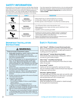
. 5 Do Not connect the operator to the source of power until instructed to do so. 6 Locate the control button: • Within sight of door. • At a minimum height of 5 feet, so small children cannot reach it. • Away from all moving parts of the door. 7 Install the entrapment WARNING label next to the wall - Genie PowerLift | Owner's Manual - Page 3
by a Genie Factory Authorized Dealer. Door springs, cables, pulleys, brackets and associated hardware are under extreme tension and can cause serious injury or death. NOTE The Excelerator Opener is equipped with an automatic Garage Door Balance Detection System. See Troubleshooting Guide on page - Genie PowerLift | Owner's Manual - Page 4
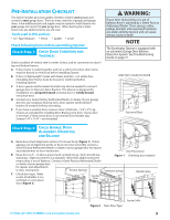
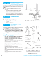
contact your Customer Service Representative at 1-800-35-GENIE. Check Step 4: CHECK DOOR HEADER AREA NOTE The header is a heavily reinforced section of the wall just above the top of the garage door opening. A Find vertical center line of door and header: • Close door. • Measure door width at top - Genie PowerLift | Owner's Manual - Page 5
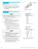
120 Volt grounded outlet or wiring box within 3 feet of Power Head. 10' for 7-1/2' doors 11' for 8' doors Door Center Line Figure 5 Check Power Head location OPEN BEAM CEILING EX AMPLES Mounting Straps 30 55 11 Support board added for longer spans 30 Perforated Angle Iron 30 FINISHED CEILINGS - Genie PowerLift | Owner's Manual - Page 6
Excelerator Extension Kit (for 8' garage doors) (store) ❐ Sufficient angle iron or strapping for hanging Power Head (store) ❐ Two 60 Watt light bulbs (Rough service bulbs recommended)(store) ❐ GER-2 Emergency Release Kit for entry during power failure (store) ❐ Wood for header, ceiling, and/or door - Genie PowerLift | Owner's Manual - Page 7
manual as required. POWER HEAD ASSEMBLY EXPLODED VIEW [1] 1A 1C 1K 1D 1B 1G 1E 1L Model Number Serial Number 1M 1H 1P POWER HEAD ASSEMBLY PARTS LIST Item 1A 1B 1C 1D 1E 1G 1H 1K 1L 1M 1P Part Name Lens Top Plate Assembly Light Socket (2) Motor Assembly Cover Motor Drive Board Controller Board - Genie PowerLift | Owner's Manual - Page 8
EXCELERATOR HARDWARE EXPLODED VIEW NOTE Opener will not function unless Safe-T-Beam® System is installed and Force Controls are properly set. One-Piece Rail Assembly (Genie Pro only) for 10' or 12' door includes: • Special "Close" Limit Switch with longer Wires. • 96" Emergency Release Cord (yellow - Genie PowerLift | Owner's Manual - Page 9
GARAGE DOOR OPENER ASSEMBLY Assembly Step C1H: CONNECT RAIL TO POWER HEAD OPEN BLUE PARTS BAG A Turn Power Head upside down and place on a flat level surface. B Install Bumper (Figure 9). C Install Coupler on Motor Shaft (Figure 9). CAUTION The Drive Screw and Rail Liner can slide out of Rail - Genie PowerLift | Owner's Manual - Page 10
Step C6H: INSTALL AND CONNECT LIMIT SWITCHES OPEN GREEN PARTS BAG A Turn Opener right side up and support Power Head to avoid damaging the Light Bulb Sockets. B Uncoil Limit Switch Wires and retain Twist Ties. #8-32 x 1" Hex Head Screws Open Limit Switch Assembly 22 Wire Clips 53 19Brown Wire - Genie PowerLift | Owner's Manual - Page 11
(white). • Terminal 5: OPEN Limit Switch Wire (white) and CLOSE Limit Switch Wire (brown). • Terminal 6: CLOSE Limit Switch Wire (brown). Antenna Terminal Block White Limit Brown Limit Switch wires Switch wires Figure 15 Connect Limit Switch Wires to Power Head Terminal Block Assembly Step C7H - Genie PowerLift | Owner's Manual - Page 12
DOOR OPENER INSTALLATION NOTE For lightweight garage doors, make sure you have installed the proper reinforcement (See Check Door Condition and Thickness on page 3). Installation SteCpH1: INSTALL HEADER BRACKET Mount directly into header Center Line of door Use of Header Bracket support board - Genie PowerLift | Owner's Manual - Page 13
as high as possible or on top of door. B Attach Door Bracket: • For metal doors, use 3 (1/4" -20 x 3/4") Self-Drilling Screws. • For wood doors, use 3 (1/4" x 2") Lag Screws. Installation SteCpH3: ATTACH RAIL TO HEADER BRACKET A While supporting the Power Head, place threaded end of Rail Strap Bolt - Genie PowerLift | Owner's Manual - Page 14
and support Opener Power Head (along door center line) higher than highest point of door travel (using step ladder, etc.) (Figure 21). B Measure distance from Opener to garage ceiling. CAUTION Mounting Brackets must be fastened to garage framing. Do Not fasten to drywall, particle board, plaster - Genie PowerLift | Owner's Manual - Page 15
SteCpH5: ASSEMBLE AND CONNECT DOOR ARMS OPEN YELLOW PARTS BAG For sectional doors: A Attach Curved Door Arm to Door Bracket with Clevis Pin and Cotter Pin (Figure 23). B Attach Straight Door Arm to Magnetic Carriage Assembly. C Attach both Arms together with 2 (3/8" x 7/8") Hex Head Bolts and - Genie PowerLift | Owner's Manual - Page 16
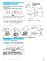
place Top of 6" Bracket 6" above floor Figure 25 Install Safe-T-Beams® SUN RED LED GREEN LED GREEN LED RED RED LED LED GREEN LED ONE DOOR GARAGE TWO DOOR GARAGE GREEN LED RED RED LED LED GREEN GREEN LED LED RED LED THREE DOOR GARAGE Figure 26 Source/sensor Locations Top edge of - Genie PowerLift | Owner's Manual - Page 17
on Power Head Terminal Block. It does not matter which Wire, white or striped, goes on which Terminal. • Check the following. - Ensure that no part of door or its hardware is in path between Source or Sensor Lenses. • Ensure that tops of Lenses are between 5" - 6" above floor. Brackets are flexible - Genie PowerLift | Owner's Manual - Page 18
Independent Light Control allows convenient manual control of Opener Lighting System. B Find a convenient mounting location: • Within direct sight of garage door. • At least 5' above floor (to prevent small children from operating garage door). • Away from any moving garage door or Opener parts (you - Genie PowerLift | Owner's Manual - Page 19
to Power Head Wires. - White supply line to Opener White Wire. - Black supply line to Opener Black Wire. - Ground to Opener Green Wire. - Replace Motor Cover. Knockout Cut Wires here NOTE • Use only Underwriters Laboratories, Inc. (U.L.) recognized wire nuts. • The Circuit Boards are light - Genie PowerLift | Owner's Manual - Page 20
. • Re-engage Magnetic Carriage Assembly. Setting Force Controls and Final Adjustment of Limit Switches WARNING • The garage door opens rapidly, and can cause serious injury or death. • Keep the path clear. • Position the ladder to the side of the Power Head so it is clear of all moving parts of the - Genie PowerLift | Owner's Manual - Page 21
REVERSE FUNCTION NOTE Limit Switch and Force Adjustments must be completed before checking the contact reverse function (Figure 36). A Open garage door using Wall Console. B Lay a 2" x 4" board flat in center of doorway. C Close door using Wall Console. D Check that door stops and reverses within - Genie PowerLift | Owner's Manual - Page 22
stops at the end of the open or close cycle. C Press Button again. Garage door will reverse. 1 Button Remote 48 2 Button Remote 51 3 Button Remote 49 Figure 37 Genie Remote Controls Learn Code Button STATUS LEARN LEARN INDICATOR LIGHT Figure 38 Learn Code Button and Indicator Light Model - Genie PowerLift | Owner's Manual - Page 23
Reverse does not work properly 1 Close door and disconnect the Opener using Emergency Release Cord. 2 Do not use door Opener, Remote Controls, or Wireless Keypad. 3 Refer to Door and Door Opener Owner's Manuals before attempting any repairs. NOTE FOR CONVENIENCE - Program Keypad BEFORE mounting - Genie PowerLift | Owner's Manual - Page 24
doors. • Enter your PIN. • Press . • Press door opener number ( or or ). SEE NOTE AT TOP OF PREVIOUS COLUMN MOUNTING INSTRUCTIONS The Keypad must be mounted in sight of the door(s), at least 5 feet above the ground and clear of any moving door parts. A Mount Keypad.(Mounting screws located - Genie PowerLift | Owner's Manual - Page 25
35-GENIE. - Reattach Magnetic Carriage Assembly to Rail Assembly: a. Pull the Emergency Release Knob toward Power Head. b. Close door. • Contact Reverse Test. - Perform Installation Step 10 on page 21. WARNING If the door fails to reverse on contact with the board, adjust the Close Force Control as - Genie PowerLift | Owner's Manual - Page 26
a Genie Factory Authorized Dealer make repairs to cables, spring assemblies, and other hardware. 8 SAVE THESE INSTRUCTIONS. WARNING Use the Wall Console included with Opener. Any other wall console can cause the Opener to operate unexpectedly and the light to stop working. TROUBLESHOOTING GUIDE - Genie PowerLift | Owner's Manual - Page 27
System Self-Diagnostic Troubleshooting • See Status Light on Figure38, page 22) You See 1 BLINK, Pause (Repeat) Problem Motor Drive Board Interrupt Normal operation restored What to Do • Reset Opener-unplug (or disconnect power), wait 5 seconds, plug back in (reapply power), and activate from - Genie PowerLift | Owner's Manual - Page 28
Check the Status LED Light) Problem What To Do Opener does not run from Remote Control 1. Check power source. A. If Opener is connected to an outlet: • Plug a working lamp into outlet used for Power Head. • If lamp glows, power source and outlet are OK. • If not, check fuse or circuit breaker or - Genie PowerLift | Owner's Manual - Page 29
be in UNLOCKED position for Opener to open door. WIRING DIAGRAM WARNING Opening Cover May Cause Electric Shock WALL CONTROL CONTROLLER BOARD GREEN PRIMARY GROUND MOTOR DRIVE BOARD LINE PLUG WHITE STRIPE BROWN BROWN WHITE WHITE OPEN LIMIT CLOSE LIMIT For Help, call 1-800-35-GENIE or visit www - Genie PowerLift | Owner's Manual - Page 30
Owner's Manual. For How Long: H8000D Series - Lifetime* on motor, on parts and service. ISD990 Series - Lifetime* on motor, 5 years* on parts. ISD990-2 Series - Lifetime* on motor and all parts. ISD995 Series - Lifetime* on motor and all parts. ISD995-2WKM Series - Lifetime* on motor and all parts - Genie PowerLift | Owner's Manual - Page 31
rallonge du Excelerator Screw Drive - Rallonge de 30 dm (18 po) prolongeant la course de l'ouvre-porte Screw Drive pour une porte de 2,4 m (8 pi) de hauteur (GIRU-1T) Universal Conversion Kit - Converts any Garage Door Opener to a secure radio signal system. Kit includes a Remote Control, Receiver - Genie PowerLift | Owner's Manual - Page 32
95 3-Button Mini Remote Control with Intellicode® GMI-3 Minicontrolador remoto de 3 funciones con Intellicode® Mini télécommande à 3 fonctions avec Intellicode® 34909R $39.95 GWKP Wireless Keypad Entry System Sistema de entrada por teclado numérico inalámbrico Système d'ouvre-porte de garage
-
 1
1 -
 2
2 -
 3
3 -
 4
4 -
 5
5 -
 6
6 -
 7
7 -
8
-
9
-
10
-
11
-
12
-
13
-
14
-
15
-
16
-
17
-
18
-
19
-
20
-
21
-
22
-
23
-
24
-
25
-
26
-
27
-
28
-
29
-
30
-
31
-
32
 |
 |

For 7' 6" Doors. Extension Kit is available for 8' Doors
Included Wall Control MUST be installed prior to Operation
of this Garage Door Operator.
Safe-T-Beam
®
Safety Reverse System Must be Installed and
the Force Controls MUST be Properly Set to close door.
This Equipment meets or exceeds all Federal,State and UL325
Safety Requirements.
Will not operate twice as fast on a one-piece door.
3531835447
SAVE THIS MANUAL FOR
FUTURE REFERENCE
C
OMPLETE WITH
INTELLICODE®
R
EMOTE
C
ONTROL AND
SERIES II
E
LECTRONICS
Having Difficulty? Need Help?
Please call us: 1-800-35-GENIE (354-3643)
www.geniecompany.com
Please have Model information ready when calling
.
Safety Information . . . . . . . . . . . . . . . . . . . . . . 2
Important Installation Instructions . . . . . . 2
Safety Features . . . . . . . . . . . . . . . . . . . . . . . . . 2
Pre-installation Checklist. . . . . . . . . . . . . . . . 3
Garage Door Opener Assembly . . . . . . . . . 9
Record Data (for Service) . . . . . . . . . . . . . . 11
Garage Door Opener Installation . . . . . . . 12
Accessories
. . . . . . . . . . . . . . . . . . . . . . . . . . . 22
Maintenance
. . . . . . . . . . . . . . . . . . . . . . . . . . 25
Troubleshooting
. . . . . . . . . . . . . . . . . . . . . . 26
Wiring Diagram . . . . . . . . . . . . . . . . . . . . . . . 29
Warranty information . . . . . . . . . . . . . . . . . . 30
T
ABLE OF
C
ONTENTS