Genie PowerLift Owner's Manual - Page 10
Assembly Step 3, Assembly Step 4, Assembly Step 5, Assembly Step 6, OPEN GREEN PARTS BAG - magnets
 |
View all Genie PowerLift manuals
Add to My Manuals
Save this manual to your list of manuals |
Page 10 highlights
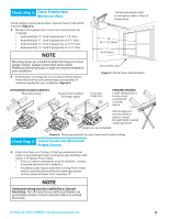
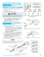
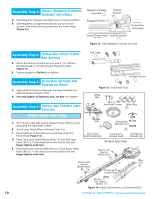
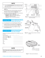
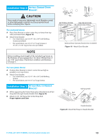
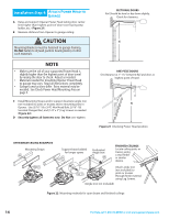
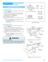
Assembly Step C3H: INSTALL MAGNETIC CARRIAGE ASSEMBLY ONTO RAILS A Place Magnetic Carriage Assembly Lever in "release" position. B Slide Magnetic Carriage Assembly into slot on End Rail Section with arrow pointing away from the Power Head (Figure 12). Magnetic Carriage Assembly 12 Engaged Position Release Position Puerta Door Porte Toward door and header Toward Power Head End Rail Section 4C Figure 12 Slide Magnetic Carriage onto Rail Assembly Step C4H: ATTACH RAIL STRAP TO END RAIL SECTION Rail Strap 15 16 A Attach Rail Strap to End Rail Section with 2 (1/4"-20) Hex Head Bolts and 2 (1/4"-20) Serrated Flange Hex Nuts (Figure 13). B Tighten snugly but Do Not over-tighten. Assembly Step C5H: ALIGN RAIL SECTIONS AND TIGHTEN ALL BOLTS A Align all Rail Sections so Magnetic Carriage Assembly can slide freely along length of Rail. B Securely tighten all fasteners now. Do Not over-tighten. End Rail Section 4C 8 Figure 13 Attach Rail Strap White Wire 21 Assembly Step C6H: INSTALL AND CONNECT LIMIT SWITCHES OPEN GREEN PARTS BAG A Turn Opener right side up and support Power Head to avoid damaging the Light Bulb Sockets. B Uncoil Limit Switch Wires and retain Twist Ties. #8-32 x 1" Hex Head Screws Open Limit Switch Assembly 22 Wire Clips 53 19Brown Wire 24 Emergency Release Cord 25 C Place Switches on Rail with arrows pointing away from Power Head (Figure 14). D Place Close Limit Switch (Brown Wire) 15" from Rail Strap. Insert (#8-32 x 1") Hex Head Screw into Switch hole and finger-tighten until later. Close Limit Switch Assembly Emergency Release Knob Emergency Release Tag Hardware (green bag) E Place Open Limit Switch (White Wire) 15" from Power Head. Insert (#8-32 x 1") Hex Head Screw into Switch hole and finger-tighten until later. Close Limit Switch (Brown wire) 19 DOOR Open Limit Switch (White wire) 18 DOOR 15" Arrows point DOOR toward door Wire Clip 53 15" #8-32 x 1" Hex Head Screws 21 Figure 14 Install Limit Switches on Assembled Rail 10 For Help, call 1-800-35-GENIE or visit www.geniecompany.com
-
 1
1 -
2
-
3
-
4
-
 5
5 -
 6
6 -
 7
7 -
 8
8 -
 9
9 -
 10
10 -
 11
11 -
 12
12 -
 13
13 -
 14
14 -
 15
15 -
16
-
17
-
18
-
19
-
20
-
21
-
22
-
23
-
24
-
25
-
26
-
27
-
28
-
29
-
30
-
31
-
32
 |
 |
