Gigabyte G1.Sniper M3 User Manual - Page 28
F_AUDIO Front Panel Audio Header, F_USB1/F_USB2/F_USB3 USB 2.0/1.1 Headers - ga
 |
View all Gigabyte G1.Sniper M3 manuals
Add to My Manuals
Save this manual to your list of manuals |
Page 28 highlights
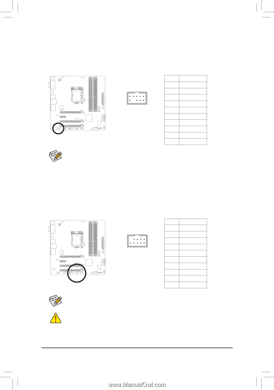
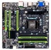
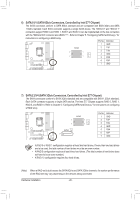
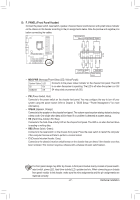
9) F_AUDIO (Front Panel Audio Header) The front panel audio header supports Intel High Definition audio (HD). You may connect your chassis front panel audio module to this header. Make sure the wire assignments of the module connector match the pin assignments of the motherboard header. Incorrect connection between the module connector and the motherboard header will make the device unable to work or even damage it. F_AUDIO(H) 9 1 10 2 Pin No. Definition 1 MIC2_L 2 GND F_PAN3EL(NH) MIC2_R G.QBO4FM -ACZ_DET 5 LINE2_R 6 GND 7 FAUDIO_JD 8 No Pin 9 LINE2_L 10 GND Some chassis provide a front paneBl IaOuSdSiwoitcmheord(Xu5le8At-OhaC)t has separated connectors on each wire inDsBte_PaOdRoTf a single plug. For information about connecting the front panel audio module that has different wire assignments, please contac1 t the chassis manufacturer. M_SATA DIP 1 23 1 DIP 1 23 1 DIP 1 23 1 Voltage measurement module(X58A-OC) 10) F_USB1/F_USB2/F_USB3 (USB 2.0/1.P1WHMeSawidtceh r(Xs5)8A-OC) The headers conform to USB 2.0/1.1 specification. Each USB header can provide two USB ports via an optional USB bracket. For purchasing the optional USB bracket, please contact the local dealer. DIP 1 23 PCIe power connector (SATA)(X58A-OC) 9 1 10 2 Voltage measurement points(G1.Sniper 3) BIOS Switcher (SW4) Pin No. 1 2 3 4 5 6 7 8 9 10 Definition Power (5V) Power (5V) USB DXUSB DYUSB DX+ USB DY+ GND GND No Pin NC When the system is in S4/S5 mode, only the USB ports routed to the F_USB1 header can support the ON/OFF Charge function. •• Do not plug the IEEE 1394 bracket (2x5-pin) cable into the USB 2.0/1.1 header. •• Prior to installing the USB bracket, be sure to turn off your computer and unplug the power cord from the power outlet to prevent damage to the USB bracket. F_PANEL (H61M-D2) ACPI_CPT (GA-IVB) SMB_CPT (GA-IVB) CLR_CMOS CI DIS_ME GP15_CPT (GA-IVB) XDP_CPU XDP_PCH (GA-IVB) Hardware Installation - 28 -
-
 1
1 -
2
-
3
-
4
-
5
-
6
-
7
-
8
-
9
-
10
-
11
-
12
-
13
-
14
-
15
-
16
-
17
-
18
-
19
-
20
-
21
-
22
-
 23
23 -
 24
24 -
 25
25 -
 26
26 -
 27
27 -
 28
28 -
 29
29 -
 30
30 -
 31
31 -
 32
32 -
 33
33 -
34
-
35
-
36
-
37
-
38
-
39
-
40
-
41
-
42
-
43
-
44
-
45
-
46
-
47
-
48
-
49
-
50
-
51
-
52
-
53
-
54
-
55
-
56
-
57
-
58
-
59
-
60
-
61
-
62
-
63
-
64
-
65
-
66
-
67
-
68
-
69
-
70
-
71
-
72
-
73
-
74
-
75
-
76
-
77
-
78
-
79
-
80
-
81
-
82
-
83
-
84
-
85
-
86
-
87
-
88
-
89
-
90
-
91
-
92
-
93
-
94
-
95
-
96
-
97
-
98
-
99
-
100
-
101
-
102
-
103
-
104
 |
 |