Gigabyte GA-H110TN-M User Manual - Page 15
F_PANEL Front Panel Header, VGA D-Sub Header, Hard Drive Activity LED, Blue
 |
View all Gigabyte GA-H110TN-M manuals
Add to My Manuals
Save this manual to your list of manuals |
Page 15 highlights
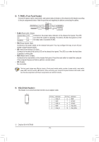
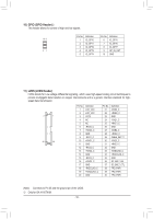
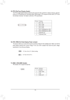
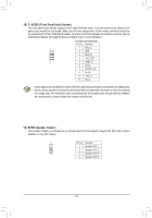
8) F_PANEL (Front Panel Header) Connect the power switch, reset switch, and system status indicator on the chassis to this header according to the pin assignments below. Note the positive and negative pins before connecting the cables. Power Switch Power LED 10 9 PWPW+ PLEDPLED+ 21 NC RES+ RESHD- HD+ Reset Switch Hard Drive Activity LED •• PLED (Power LED, Yellow): System Status LED Connects to the power status indicator on the chassis front panel. The LED S0 On S3/S4/S5 Off is on when the system is operating. The LED is off when the system is in S3/ S4 sleep state or powered off (S5). •• PW (Power Switch, Red): Connects to the power switch on the chassis front panel. You may configure the way to turn off your system using the power switch. •• HD (Hard Drive Activity LED, Blue): Connects to the hard drive activity LED on the chassis front panel. The LED is on when the hard drive is reading or writing data. •• RES (Reset Switch, Green): Connects to the reset switch on the chassis front panel. Press the reset switch to restart the computer if the computer freezes and fails to perform a normal restart. •• NC (Purple): No connection. The front panel design may differ by chassis. A front panel module mainly consists of power switch, reset switch, power LED, hard drive activity LED and etc. When connecting your chassis front panel module to this header, make sure the wire assignments and the pin assignments are matched correctly. 9) VGA (D-Sub Header)j This header is to connect a D-Sub monitor via an adapter cable. 21 Pin No. Definition 1 VGA_R 2 GND 10 9 3 VGA_G 4 GND 5 VGA_B Pin No. 6 7 8 9 10 Definition GND HSYNC VSYNC VGA_SCL VGA_SDA j Only for GA-H110TN-M. - 15 -
-
 1
1 -
2
-
3
-
4
-
5
-
6
-
7
-
8
-
9
-
 10
10 -
 11
11 -
 12
12 -
 13
13 -
 14
14 -
 15
15 -
 16
16 -
 17
17 -
 18
18 -
 19
19 -
 20
20 -
21
-
22
-
23
-
24
-
25
-
26
-
27
-
28
-
29
-
30
-
31
-
32
-
33
-
34
-
35
-
36
-
37
-
38
-
39
-
40
-
41
 |
 |
