Gigabyte GA-H110TN-M User Manual - Page 20
SPEAKER Buzzer Header, F_USB1/F_USB2 USB 2.0/1.1 Headers, COMC/COMD Serial Port Headers
 |
View all Gigabyte GA-H110TN-M manuals
Add to My Manuals
Save this manual to your list of manuals |
Page 20 highlights
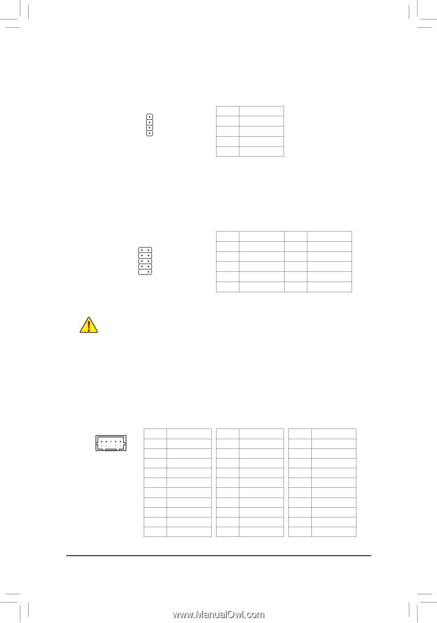
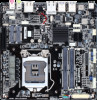
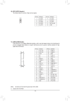
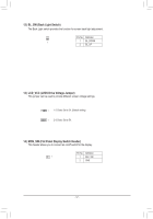
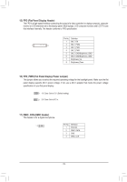
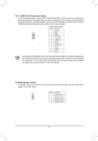
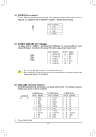
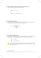
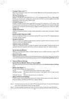
20) SPEAKER (Buzzer Header) Connects to the buzzer on the chassis front panel. The system reports system startup status by issuing a beep code. One single short beep will be heard if no problem is detected at system startup. Pin No. Definition 1 VCC 2 NC 1 3 NC 4 SPK- 21) F_USB1/F_USB2 (USB 2.0/1.1 Headers) The headers conform to USB 2.0/1.1 specification. Each USB header can provide two USB ports via an optional USB bracket. For purchasing the optional USB bracket, please contact the local dealer. 1 2 9 10 Pin No. 1 2 3 4 5 Definition Power (5V) Power (5V) USB DXUSB DYUSB DX+ Pin No. 6 7 8 9 10 Definition USB DY+ GND GND No Pin NC •• Do not plug the IEEE 1394 bracket (2x5-pin) cable into the USB header. •• Prior to installing the USB bracket, be sure to turn off your computer and unplug the power cord from the power outlet to prevent damage to the USB bracket. 22) COMC/COMD (Serial Port Headers)j Each COM header can provide one serial port via an optional COM port cable. For purchasing the optional COM port cable, please contact the local dealer. For RS232 Devices: Pin No. Definition 10 9 2 1 1 NDCD- 2 NDSR- 3 NSIN 4 NRTS- 5 NSOUT 6 NCTS- 7 NDTR- 8 +5V/+12V 9 GND 10 NC j Only for GA-H110TN-M. For RS422 Devices: Pin No. Definition 1 TX(B) 2 NC 3 TX(A) 4 NC 5 RX(A) 6 NC 7 RX(B) 8 +5V/+12V 9 GND 10 NC - 20 - For RS485 Devices: Pin No. Definition 1 D2 NC 3 D+ 4 NC 5 NC 6 NC 7 NC 8 +5V/+12V 9 GND 10 NC
-
 1
1 -
2
-
3
-
4
-
5
-
6
-
7
-
8
-
9
-
10
-
11
-
12
-
13
-
14
-
 15
15 -
 16
16 -
 17
17 -
 18
18 -
 19
19 -
 20
20 -
 21
21 -
 22
22 -
 23
23 -
 24
24 -
 25
25 -
26
-
27
-
28
-
29
-
30
-
31
-
32
-
33
-
34
-
35
-
36
-
37
-
38
-
39
-
40
-
41
 |
 |