Gigabyte GA-K8NSNXP User Manual - Page 22
ATX_12V +12V Power Connector, ATX ATX Power Connector
 |
View all Gigabyte GA-K8NSNXP manuals
Add to My Manuals
Save this manual to your list of manuals |
Page 22 highlights
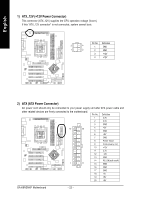
English 1) ATX_12V (+12V Power Connector) This connector (ATX_12V) supplies the CPU operation voltage (Vcore). If this "ATX_12V connector" is not connected, system cannot boot. Pin No. Definition 3 4 1 GND 1 2 2 GND 3 +12V 4 +12V 2) ATX (ATX Power Connector) AC power cord should only be connected to your power supply unit after ATX power cable and other related devices are firmly connected to the motherboard. Pin No. Definition 1 3.3V 2 3.3V 3 GND 10 20 4 +5V 5 GND 6 +5V 7 GND 8 Power Good 9 5V SB (stand by +5V) 10 +12V 11 3.3V 12 -12V 13 GND 14 PS_ON(soft on/off) 1 11 15 GND 16 GND 17 GND 18 -5V 19 +5V 20 +5V GA-K8NSNXP Motherboard - 22 -
-
 1
1 -
2
-
3
-
4
-
5
-
6
-
7
-
8
-
9
-
10
-
11
-
12
-
13
-
14
-
15
-
16
-
 17
17 -
 18
18 -
 19
19 -
 20
20 -
 21
21 -
 22
22 -
 23
23 -
 24
24 -
 25
25 -
 26
26 -
 27
27 -
28
-
29
-
30
-
31
-
32
-
33
-
34
-
35
-
36
-
37
-
38
-
39
-
40
-
41
-
42
-
43
-
44
-
45
-
46
-
47
-
48
-
49
-
50
-
51
-
52
-
53
-
54
-
55
-
56
-
57
-
58
-
59
-
60
-
61
-
62
-
63
-
64
-
65
-
66
-
67
-
68
-
69
-
70
-
71
-
72
-
73
-
74
-
75
-
76
-
77
-
78
-
79
-
80
-
81
-
82
-
83
-
84
-
85
-
86
-
87
-
88
-
89
-
90
-
91
-
92
-
93
-
94
-
95
-
96
 |
 |

- 22 -
GA-K8NSNXP Motherboard
English
1)
ATX_12V (+12V Power Connector)
This connector (ATX_12V) supplies the CPU operation voltage (Vcore).
If this "ATX_12V connector" is not connected, system cannot boot.
2)
ATX (ATX Power Connector)
AC power cord should only be connected to your power supply unit after ATX power cable and
other related devices are firmly connected to the motherboard.
1
20
10
11
4
3
2
1
Pin No.
Definition
1
3.3V
2
3.3V
3
GND
4
+5V
5
GND
6
+5V
7
GND
8
Power Good
9
5V SB (stand by +5V)
10
+12V
11
3.3V
12
-12V
13
GND
14
PS_ON(soft on/off)
15
GND
16
GND
17
GND
18
-5V
19
+5V
20
+5V
Pin No.
Definition
1
GND
2
GND
3
+12V
4
+12V