Gigabyte GA-M68SM-S2 Manual
Gigabyte GA-M68SM-S2 Manual
 |
View all Gigabyte GA-M68SM-S2 manuals
Add to My Manuals
Save this manual to your list of manuals |
Gigabyte GA-M68SM-S2 manual content summary:
- Gigabyte GA-M68SM-S2 | Manual - Page 1
GA-M68SM-S2 AM2 socket motherboard for AMD AthlonTM 64 FX processor/ AMD AthlonTM 64 X2 Dual-Core processor/ AMD AthlonTM 64 processor/AMD SempronTM processor User's Manual Rev. 1002 12ME-M68SMS2-1002R * The WEEE marking on the product indicates this product must not be disposed of with user's other - Gigabyte GA-M68SM-S2 | Manual - Page 2
Motherboard GA-M68SM-S2 Jul. 27, 2007 Motherboard GA-M68SM-S2 Jul. 27, 2007 - Gigabyte GA-M68SM-S2 | Manual - Page 3
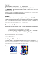
of documentations: „ For detailed product information, carefully read the User's Manual. „ For instructions on how to use GIGABYTE's unique features, read or download the information on/from the Support\Motherboard\Technology Guide page on our website. For product-related information, check on - Gigabyte GA-M68SM-S2 | Manual - Page 4
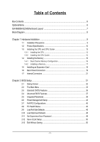
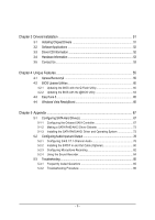
...6 GA-M68SM-S2 Motherboard Layout 7 Block Diagram ...8 Chapter 1 Hardware Installation 9 1-1 Installation Precautions 9 1-2 Product Specifications 10 1-3 Installing the CPU and CPU Cooler 13 1-3-1 Installing the CPU 13 1-3-2 Installing the CPU Cooler 15 1-4 Installing the Memory 16 - Gigabyte GA-M68SM-S2 | Manual - Page 5
Utility 60 4-2-2 Updating the BIOS with the @BIOS Utility 63 4-3 EasyTune 5 ...65 4-4 Windows Vista ReadyBoost 66 Chapter 5 Appendix ...67 5-1 Configuring SATA Hard Drive(s 67 5-1-1 Configuring the Onboard SATA Controller 67 5-1-2 Making a SATA RAID/AHCI Driver Diskette 72 5-1-3 Installing - Gigabyte GA-M68SM-S2 | Manual - Page 6
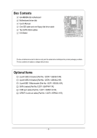
Box Contents GA-M68SM-S2 motherboard Motherboard driver disk User's Manual One IDE cable and one floppy disk drive cable Two SATA 3Gb/s cables I/O Shield The box contents above are for reference only and the actual - Gigabyte GA-M68SM-S2 | Manual - Page 7
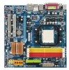
GA-M68SM-S2 Motherboard Layout KB_MS ATX_12V ATX Socket AM2 CPU_FAN DVI LPT VGA USB USB LAN 1394 IT8716 AUDIO F_AUDIO PCIE_16 PCIE_1 RTL 8211BL PCI1 CD_IN CODEC PCI2 SPDIF_IO GA-M68SM-S2 CI BATTERY BIOS CLR_CMOS COM F1_1394 TSB43AB23 DDRII_1 DDRII_2 DDRII_3 DDRII_4 IDE FDD - Gigabyte GA-M68SM-S2 | Manual - Page 8
MHz) AMD Socket AM2 CPU CPU CLK+/-(200 MHz) DDR2 800/667/533 MHz DIMM Hyper Transport Bus Dual Channel Memory PCI Express x16 DVI-D PCI Express Bus x1 PCIe CLK (100 MHz) 1 PCI Express x1 PCI Bus TSB43AB23 2 IEEE 1394a nVIDIA® GeForce 7025/ nForce 630a D-Sub RTL 8211BL LAN RJ45 4 SATA 3Gb - Gigabyte GA-M68SM-S2 | Manual - Page 9
user's manual and follow these procedures: • Prior to installation, do not remove or break motherboard strap when handling electronic components such as a motherboard, CPU or memory. If you do not have an ESD to the user. • If you are uncertain about any installation steps or have a problem related to - Gigabyte GA-M68SM-S2 | Manual - Page 10
Bus Chipset Memory Audio LAN Expansion Slots Storage Interface IEEE 1394 USB Š Support for Socket AM2 processors: AMD AthlonTM 64 FX processor/AMD AthlonTM 64 X2 Dual-Core processor/ AMD AthlonTM 64 processor/AMD SempronTM processor (Go to GIGABYTE's website for the latest CPU support list.) Š 2000 - Gigabyte GA-M68SM-S2 | Manual - Page 11
System voltage detection Š CPU/System temperature detection Š CPU/System fan speed detection Š CPU/System overheating warning Š CPU/System fan fail warning Š CPU fan speed control (Note 2) BIOS Š 1 x 4 Mbit flash Š Use of licensed AWARD BIOS Š PnP 1.0a, DMI 2.0, SM BIOS 2.4, ACPI 1.0b - 11 - Gigabyte GA-M68SM-S2 | Manual - Page 12
GB of physical memory is installed, the actual memory size displayed will be less than 4 GB. (Note 2) Whether the CPU fan speed control function is supported will depend on the CPU you install. (Note 3) Available functions in Easytune may differ by motherboard model. GA-M68SM-S2 Motherboard - 12 - - Gigabyte GA-M68SM-S2 | Manual - Page 13
before you begin to install the CPU: • Make sure that the motherboard supports the CPU. (Go to GIGABYTE's website for the latest CPU support list.) • Always turn off the computer and unplug the power cord from the power outlet before installing the CPU to prevent hardware damage. • Locate the - Gigabyte GA-M68SM-S2 | Manual - Page 14
its socket, place one finger down on the middle of the CPU, lowering the locking lever and latching it into the fully locked position. Do not force the CPU into the CPU socket. The CPU cannot fit in if oriented incorrectly. Adjust the CPU orientation if this occurs. GA-M68SM-S2 Motherboard - 14 - - Gigabyte GA-M68SM-S2 | Manual - Page 15
lock into place. (Refer to your CPU cooler installation manual for instructions on installing the cooler.) Step 5: Finally, attach the power connector of the CPU cooler to the CPU fan header (CPU_FAN) on the motherboard. Use extreme care when removing the CPU cooler because the thermal grease/tape - Gigabyte GA-M68SM-S2 | Manual - Page 16
guidelines before you begin to install the memory: • Make sure that the motherboard supports the memory. It is recommended that memory of the same capacity, brand, speed, and chips be used. (Go to GIGABYTE's website for the latest memory support list.) • Always turn off the computer and unplug - Gigabyte GA-M68SM-S2 | Manual - Page 17
the computer and unplug the power cord from the power outlet to prevent damage to the memory module. DDR2 DIMMs are not compatible to DDR DIMMs. Be sure to install DDR2 DIMMs on this motherboard. Notch DDR2 DIMM A DDR2 memory module has a notch, so it can only fit in one direction. Follow the steps - Gigabyte GA-M68SM-S2 | Manual - Page 18
expansion card: • Make sure the motherboard supports the expansion card. Carefully read the manual that came with your expansion card. necessary, go to BIOS Setup to make any required BIOS changes for your expansion card(s). 7. Install the driver provided with the GA-M68SM-S2 Motherboard - 18 - - Gigabyte GA-M68SM-S2 | Manual - Page 19
connector. Connect a monitor that supports D-Sub connection to this port. • This motherboard provides two ports for video output, DVI and D-Sub, and supports dual view function. • Due to an nVIDIA GeForce 7025/nForce 630a chipset limitation, the GA-M68SM-S2 does not support dual view function via - Gigabyte GA-M68SM-S2 | Manual - Page 20
to perform different functions via the audio software. Only microphones still MUST be connected to the default Mic in jack ( ). Refer to the instructions on setting up a 2/4/5.1/ 7.1-channel audio configuration in Chapter 5, "Configuring 2/4/5.1/7.1-Channel Audio." GA-M68SM-S2 Motherboard - 20 - - Gigabyte GA-M68SM-S2 | Manual - Page 21
devices. • After installing the device and before turning on the computer, make sure the device cable has been securely attached to the connector on the motherboard. - 21 - Hardware Installation - Gigabyte GA-M68SM-S2 | Manual - Page 22
The 12V power connector mainly supplies power to the CPU. If the 12V power connector is not connected, compatible with power supplies with 2x10 power connectors. When using a 2x12 power supply, remove the protective cover from the main power connector on the motherboard GA-M68SM-S2 Motherboard - 22 - - Gigabyte GA-M68SM-S2 | Manual - Page 23
connection and requires a +12V voltage. The black connector wire is the ground wire. The motherboard supports CPU fan speed control, which requires the use of a CPU fan with fan speed control design. For optimum heat dissipation, it is recommended that a system fan be installed inside the - Gigabyte GA-M68SM-S2 | Manual - Page 24
supports a single SATA device. The nVIDIA® GeForce 7025/ nForce 630a controller supports RAID 0, RAID 1, RAID 0+1, RAID 5 and JBOD. Refer to Chapter 5, "Configuring SATA Hard Drive(s)," for instructions and the total number of hard drives must be an even number. GA-M68SM-S2 Motherboard - 24 - - Gigabyte GA-M68SM-S2 | Manual - Page 25
MPD- 1 3 MPD- System Status LED S0 On S1 Blinking S3/S4/S5 Off 9) BATTERY The battery provides power to keep the values (such as BIOS configurations, date, and time information) in the CMOS when the computer is turned off. Replace the battery when the battery voltage drops to a low level - Gigabyte GA-M68SM-S2 | Manual - Page 26
heard if no problem is detected at system startup. If a problem is detected, the BIOS may issue beeps in different patterns to indicate the problem. Refer to Chapter 5, "Troubleshooting," for information about and the pin assignments are matched correctly. GA-M68SM-S2 Motherboard - 26 - - Gigabyte GA-M68SM-S2 | Manual - Page 27
10 NC • The front panel audio header supports HD audio by default. If your chassis provides an AC'97 front panel audio module, refer to the instructions on how to activate AC'97 functioninality via the audio software in Chapter 5, "Configuring 2/4/5.1/7.1-Channel Audio." • When using an AC'97 - Gigabyte GA-M68SM-S2 | Manual - Page 28
optional S/PDIF in and out cable, this header can connect to an audio device that supports digital audio out and an audio system that supports digital audio in. For purchasing the optional S/PDIF in and out cable, please contact to prevent damage to the USB bracket. GA-M68SM-S2 Motherboard - 28 - - Gigabyte GA-M68SM-S2 | Manual - Page 29
English 15) F1_1394 (IEEE 1394a Headers, Gray) The headers conform to IEEE 1394a specification. Each IEEE 1394a header can provide one IEEE 1394a port via an optional IEEE 1394a bracket. For purchasing the optional IEEE 1394a bracket, please contact the local dealer. Pin No. Definition 1 TPA+ 2 - Gigabyte GA-M68SM-S2 | Manual - Page 30
the jumper. Failure to do so may cause damage to the motherboard. • After system restart, go to BIOS Setup to load factory defaults (select Load Optimized Defaults) or manually configure the BIOS settings (refer to Chapter 2, "BIOS Setup," for BIOS configurations). GA-M68SM-S2 Motherboard - 30 - - Gigabyte GA-M68SM-S2 | Manual - Page 31
Windows-based utility that searches and downloads the latest version of BIOS from the Internet and updates the BIOS. For instructions on using the Q-Flash and @BIOS utilities, refer to Chapter 4, "BIOS Update Utilities." • Because BIOS flashing is potentially risky, if you do not encounter problems - Gigabyte GA-M68SM-S2 | Manual - Page 32
, the device boot order will still be based on BIOS Setup settings. You can access Boot Menu again to change the first boot device setting as needed. : Q-Flash Press the key to access the Q-Flash utility directly without having to enter BIOS Setup first. GA-M68SM-S2 Motherboard - 32 - - Gigabyte GA-M68SM-S2 | Manual - Page 33
F8: Q-Flash Load Fail-Safe Defaults Load Optimized Defaults Set Supervisor Password Set User Password Save & Exit Setup Exit Without Saving KLJI: Select Item F10: Save & Exit Setup Time, Date, Hard Disk Type... BIOS Setup Program Function Keys Move the selection bar to select an item - Gigabyte GA-M68SM-S2 | Manual - Page 34
CMOS and exit BIOS Setup. (Pressing can also carry out this task.) „ Exit Without Saving Abandon all changes and the previous settings remain in effect. Pressing to the confirmation message will exit BIOS Setup. (Pressing can also carry out this task.) GA-M68SM-S2 Motherboard - 34 - Gigabyte GA-M68SM-S2 | Manual - Page 35
A Floppy 3 Mode Support [1.44M, 3.5"] [Disabled] Halt On [All Errors] Base Memory Extended Memory 640K 239M KLJI: the three methods below: • Auto Lets BIOS automatically detect IDE/SATA devices during the faster system startup. • Manual Allows you to manually enter the specifications of - Gigabyte GA-M68SM-S2 | Manual - Page 36
manually 3 Mode Support Allows you Memory These fields are read-only and are determined by the BIOS POST. Base Memory Also called conventional memory. Typically, 640 KB will be reserved for the MS-DOS operating system. Extended Memory The amount of extended memory. GA-M68SM-S2 Motherboard - Gigabyte GA-M68SM-S2 | Manual - Page 37
F10: Save F6: Fail-Safe Defaults ESC: Exit F1: General Help F7: Optimized Defaults AMD K8 Cool&Quiet control Auto Lets the AMD Cool'n'Quiet driver dynamically adjust the CPU clock and VIA to Disabled reduce heat output from your computer and its power consumption. (Default) Disable this - Gigabyte GA-M68SM-S2 | Manual - Page 38
Windows XP Control option is set to Manual. Frame buffer size is the total amount of system memory allocated solely for the onboard graphics controller. MS-DOS, for example, will use only this memory for display. Options are: 16M, 32M, 64M(default), 128M, 256M, Disabled. GA-M68SM-S2 Motherboard - Gigabyte GA-M68SM-S2 | Manual - Page 39
-Chip MAC Lan NV Serial-ATA 1 IDE Prefetch Mode Onchip SATA Mode Onboard Audio Function Onboard 1394 ` SMART LAN OnBoard LAN Boot ROM Copyright (C) 1984-2007 Award Software USB Device Setting USB Controllers USB Keyboard Function USB Mouse Function USB Storage Function Defaults - 39 - BIOS Setup - Gigabyte GA-M68SM-S2 | Manual - Page 40
Enables or disables the onboard audio function. (Default: Auto) If you wish to install a 3rd party add-in audio card instead of using the onboard audio, set this item to Disabled. Onboard 1394 Enables or disables the onboard IEEE 1394 function. (Default: Enabled) GA-M68SM-S2 Motherboard - 40 - - Gigabyte GA-M68SM-S2 | Manual - Page 41
for diagnosing your LAN cable: When No LAN Cable Is Attached... If no LAN cable is attached to the motherboard, the Status /100/1000 Mbps in Windows mode or when the LAN Boot ROM is activated. When a Cable Problem Occurs... If a cable problem occurs on a specified LAN cable. - 41 - BIOS Setup - Gigabyte GA-M68SM-S2 | Manual - Page 42
to activate the boot ROM integrated with the onboard LAN chip. (Default: Disabled) Onboard Serial Port Enables mode. Options are: 3 (default), 1. USB Controllers Enables or disables the integrated USB controller. (Default: Enabled) Disabled will turn off all Enabled) GA-M68SM-S2 Motherboard - 42 - - Gigabyte GA-M68SM-S2 | Manual - Page 43
Power-On by Alarm x Day of Month Alarm x Time (hh:mm:ss) Alarm HPET Support (Note) HPET Mode (Note) Power On By Mouse Power On By Keyboard x KB Power from a modem that supports wake-up function. (Default: Enabled) (Note) Supported on Windows® Vista® operating system only. - 43 - BIOS Setup - Gigabyte GA-M68SM-S2 | Manual - Page 44
stays off upon the return of the AC power. (Default ) Full-On The system is turned on upon the return of the AC power. (Note) Supported on Windows® Vista® operating system only. GA-M68SM-S2 Motherboard - 44 - - Gigabyte GA-M68SM-S2 | Manual - Page 45
IRQ Assignment Auto 3,4,5,7,9,10,11,12,14,15 +/-/PU/PD: Value F10: Save F6: Fail-Safe Defaults ESC: Exit F1: General Help F7: Optimized Defaults BIOS auto-assigns IRQ to the first PCI slot. (Default) Assigns IRQ 3,4,5,7,9,10,11,12,14,15 to the first PCI slot - Gigabyte GA-M68SM-S2 | Manual - Page 46
: Disabled (default), 60oC/140oF, 70oC/158oF, 80oC/176oF, 90oC/194oF. CPU/SYSTEM FAN Fail Warning Allows the system to emit warning sound if the CPU/system fan is not connected or fails. Check the fan condition or fan connection when this occurs. (Default: Disabled) GA-M68SM-S2 Motherboard - 46 - - Gigabyte GA-M68SM-S2 | Manual - Page 47
at full speed. (Default: Enabled) CPU Smart FAN Mode Specifies how to control CPU fan speed. This item is configurable only if CPU Smart FAN Control is set to Enabled. Auto Lets BIOS autodetect the type of CPU fan installed and sets the optimal CPU fan control mode. (Default) Voltage PWM Sets - Gigabyte GA-M68SM-S2 | Manual - Page 48
Press on this item and then press the key to load the optimal BIOS default settings. The BIOS defaults settings helps the system to operate in optimum state. Always load the Optimized defaults after updating the BIOS or after clearing the CMOS values. GA-M68SM-S2 Motherboard - 48 - - Gigabyte GA-M68SM-S2 | Manual - Page 49
Setup, you must enter the supervisor password if you wish to make changes to BIOS settings. The user password only allows you to view the BIOS settings but not to make changes. To clear the password, press on the password item and when requested for the password, press again. - Gigabyte GA-M68SM-S2 | Manual - Page 50
Without Saving KLJI: Select Item F10: Save & Exit Setup Abandon all Data Press on this item and press the key. This exits the BIOS Setup without saving the changes made in BIOS Setup to the CMOS. Press or to return to the BIOS Setup Main Menu. GA-M68SM-S2 Motherboard - 50 - - Gigabyte GA-M68SM-S2 | Manual - Page 51
other drivers. • After the drivers are installed, follow the onscreen instructions to restart your system. You can install other applications included in the motherboard driver disk. • For USB 2.0 driver support under the Windows XP operating system, please install the Windows XP Service Pack - Gigabyte GA-M68SM-S2 | Manual - Page 52
all the tools and applications that GIGABYTE develops and some free software. You may press the Install button following an item to install it. 3-3 Driver CD Information This page provides information about the drivers, applications and tools in this driver disk. GA-M68SM-S2 Motherboard - 52 - - Gigabyte GA-M68SM-S2 | Manual - Page 53
English 3-4 Hardware Information This page provides information about the hardware devices on this motherboard. 3-5 Contact Us Check the contacts information of the GIGABYTE headquarter in Taiwan and the overseas branch offices on the last page of this manual. - 53 - Drivers Installation - Gigabyte GA-M68SM-S2 | Manual - Page 54
English GA-M68SM-S2 Motherboard - 54 - - Gigabyte GA-M68SM-S2 | Manual - Page 55
is recommended to back up your system soon after the operating system and drivers are installed. • The amount of data and hard drive access speed may affect At least 64 MB of system memory • VESA compatible graphics card • Windows® 2000 with SP3 or later; Windows® XP with SP1 or later • Xpress Recovery - Gigabyte GA-M68SM-S2 | Manual - Page 56
Windows XP as the example operating system.) A. Installing Windows XP and Partitioning the Hard Drive 1. Set CD-ROM drive as the first boot device under "Advanced BIOS Features" in the BIOS NTFS) and begin the installation of the operating system (Figure 3). Figure 3 GA-M68SM-S2 Motherboard - 56 - - Gigabyte GA-M68SM-S2 | Manual - Page 57
English 4. After the operating system is installed, right-click the My Computer icon on your desktop and select Manage (Figure 4). Go to Computer Management to check disk allocation. Xpress Recovery2 will save the backup file to the unallocated space (black stripe along the top)(Figure 5). Please - Gigabyte GA-M68SM-S2 | Manual - Page 58
drive contains the Windows operating system. When the Windows operating system is detected, Xpress Recovery2 will begin the backup process (Figure 11). Figure 10 Figure 11 3. When finished, go to Disk Management to check disk allocation. Figure 12 GA-M68SM-S2 Motherboard Xpress Recovery2 will - Gigabyte GA-M68SM-S2 | Manual - Page 59
English D. Using the Restore Function in Xpress Recovery2 Select RESTORE to restore the backup to your hard drive in case the system breaks down. The RESTORE option will not be present if no backup is created before (Figure 13, 14). Figure 13 Figure 14 E. Removing the Backup 1. If you wish to - Gigabyte GA-M68SM-S2 | Manual - Page 60
the Windows environment. @BIOS will download the latest BIOS file from the nearest @BIOS server site and update the BIOS. 4-2-1 Updating the BIOS with the Q-Flash Utility A. Before You Begin: 1. From GIGABYTE's website, download the latest compressed BIOS update file that matches your motherboard - Gigabyte GA-M68SM-S2 | Manual - Page 61
option allows you to save the current BIOS file. • Q-Flash only supports USB flash drive or hard drives using FAT32/16/12 file system. • If the BIOS update file is saved to a hard drive in RAID/AHCI mode or a hard drive attached to an independent IDE/SATA controller, use the key during the - Gigabyte GA-M68SM-S2 | Manual - Page 62
Without Saving KLJI: Select Item F10: Save & Exit Setup Load Optimized Defaults Press to load BIOS defaults Step 6: Select Save & Exit Setup and then press to save settings to CMOS and exit BIOS Setup. The procedure is complete after the system restarts. GA-M68SM-S2 Motherboard - 62 - - Gigabyte GA-M68SM-S2 | Manual - Page 63
and Using @BIOS: Use the motherboard driver disk included with the motherboard to install @BIOS. • Installing the @BIOS utility. • Accessing the @BIOS utility. Select @BIOS and click Install. Click Start>Program>Gigabyte>BIOS>@BIOS C. Options and Instructions: 1. Save the Current BIOS File In - Gigabyte GA-M68SM-S2 | Manual - Page 64
in an unbootable system. • If the BIOS update file for your motherboard is not present on the @BIOS server site, please manually download the BIOS update file from GIGABYTE's website and follow the instructions in "Update the BIOS without Using the Internet Update Function" below. Step 4: As the - Gigabyte GA-M68SM-S2 | Manual - Page 65
the BIOS Setup program. EasyTune 5 provides the following functions (Note 1): overclocking/overvoltage, C.I.A./ M.I.B. (Note 2), smart fan control, and hardware monitoring and warning. (For instructions on using EasyTune5, read or download the information on/from the Support\Motherboard\Utility - Gigabyte GA-M68SM-S2 | Manual - Page 66
. Click Apply and then OK to turn on ReadyBoost. • The USB flash drive must have at least 256 MB of space. • The recommended amount of memory to use for ReadyBoost acceleration is one to three times the amount of RAM installed in your computer. GA-M68SM-S2 Motherboard - 66 - - Gigabyte GA-M68SM-S2 | Manual - Page 67
controller mode in BIOS Setup. C . Configure a RAID array in RAID BIOS. (Note 1) D. Make a floppy disk containing the SATA RAID/AHCI driver. (Note 2) E. Install the SATA RAID/AHCI driver • Windows Vista/XP/2000 setup disk. • Motherboard driver disk. 5-1-1 Configuring the Onboard SATA Controller A. - Gigabyte GA-M68SM-S2 | Manual - Page 68
ESC: Exit F1: General Help F7: Optimized Defaults The BIOS Setup menus described in this section may differ from the exact settings for your motherboard. The actual BIOS Setup menu options you will see shall depend on the motherboard you have and the BIOS version. GA-M68SM-S2 Motherboard - 68 - - Gigabyte GA-M68SM-S2 | Manual - Page 69
BIOS Enter the RAID BIOS setup utility to configure a RAID array. For a non-RAID configuration, please skip this step and proceed to the installation of Windows operating system. Step 1: After the POST memory mode. The supported RAID modes include is selected, you can manually set the stripe block - Gigabyte GA-M68SM-S2 | Manual - Page 70
]..01N?..MMO ST3120026AS ST3120026AS Capacity 111.79GB 111.79GB [Y] YES [N] NO [I ] Del [ESC] Quit [F6] Back [F7] Finish [TAB] Navigate [KL] Select [ENTER] Popup Figure 6 GA-M68SM-S2 Motherboard - 70 - - Gigabyte GA-M68SM-S2 | Manual - Page 71
to confirm or to cancel. Press to return to the Array List screen. To exit the NVIDIA RAID setup utility, press in the main menu or + in the Array List screen. Now, you can proceed to the installation of the SATA controller driver and operating system. - 71 - Appendix - Gigabyte GA-M68SM-S2 | Manual - Page 72
(Note) For users without a startup disk: Use an alternative system and insert the motherboard driver disk. From your optical drive folder, double click the MENU.exe file in the BootDrv folder (Figure 3). A command prompt window will open similar to that in Figure 2. GA-M68SM-S2 Motherboard Figure - Gigabyte GA-M68SM-S2 | Manual - Page 73
you have prepared the SATA RAID/AHCI driver diskette and configured the required BIOS settings, you are ready to install Windows Vista/XP/2000 onto your hard drive(s). The following is an example of Windows XP and Vista installation. A. Installing Windows XP Step 1: Restart your system to boot from - Gigabyte GA-M68SM-S2 | Manual - Page 74
the SCSI Adapter you want from the following list, or press ESC to return to the previous screen. NVIDIA RAID Driver (required) NVIDIA nForce Storage Controller (required) ENTER=Select F3=Exit Figure 3 Windows Setup Setup will load support for the following mass storage device(s): NVIDIA RAID - Gigabyte GA-M68SM-S2 | Manual - Page 75
controller driver installation is completed, you can proceed with the Windows XP installation. WindowsXP Professional Setup Welcome to Setup. This port of the Setup program prepares Microsoft(R) Windows (R) XP to run on your computer. To set up Windows XP now, press ENTER. To repair a Windows XP - Gigabyte GA-M68SM-S2 | Manual - Page 76
steps. When a screen similar to that below appears (RAID or AHCI hard drive(s) will not be detected at this stage), select Load Drivers. (Figure 6). Figure 6 Step 2: Specify the location where the driver is saved, such as your floppy disk (Figure 7). Figure 7 GA-M68SM-S2 Motherboard - 76 - - Gigabyte GA-M68SM-S2 | Manual - Page 77
, for example, when a screen (Note) as shown in Figure 8 appears, select NVIDIA nForce RAID Controller and press Next. Figure 8 Step 4: After the driver is loaded, the screen will show the RAID or AHCI hard drive(s). Select the location where you want to install the operating system and then - Gigabyte GA-M68SM-S2 | Manual - Page 78
the Audio Control Panel. Before installing the audio driver, make sure the "Microsoft UAA Bus driver for High Definition Audio" has been installed from the motherboard driver disk and your operating system has been updated with the latest Service Pack for Windows. (Note) 2/4/5.1/7.1 Channel Audio - Gigabyte GA-M68SM-S2 | Manual - Page 79
English Step 2: Click the Audio I/O tab. In the speaker list on the left, select 2CH Speaker, 4CH Speaker, 6CH Speaker, or 8CH Speaker according to the type of speaker configuration you wish to set up. Step 3: Everytime you connect an audio device to an audio jack, the Connected device box appears. - Gigabyte GA-M68SM-S2 | Manual - Page 80
digital audio signals to an external decoder. A. Installing the S/PDIF In and Out Cable: Step 1: First, attach the connector at the end of the cable to the SPDIF_IO header on your motherboard. Step 2: Secure the metal bracket to the chassis back panel with a screw. GA-M68SM-S2 Motherboard - 80 - Gigabyte GA-M68SM-S2 | Manual - Page 81
Coaxial Cable Step 3: Connect a S/PDIF coaxial cable or a S/PDIF optical cable (either one) to an external decoder for transmitting the S/PDIF digital audio signals. S/PDIF Optical Cable C. Configuring S/PDIF out: Click the tool icon in the DIGITAL section. In the S/PDIF In/Out Settings dialog box - Gigabyte GA-M68SM-S2 | Manual - Page 82
Microphone Recording Step 1: After installing the audio driver, the Audio Manager icon will appear in your system tray. Double-click the icon to access the Audio Control Panel. Step 2: Connect your microphone to tray and click it to open the volume control panel. GA-M68SM-S2 Motherboard - 82 - - Gigabyte GA-M68SM-S2 | Manual - Page 83
Options menu and then choose Properties. Select the volume control options you wish to show and click OK to complete. Step 5: Next, while in Master Volume, go to Options and click Properties. In the Mixer device list, select Realtek HD Audio Input. Then set the recording sound level properly. Do - Gigabyte GA-M68SM-S2 | Manual - Page 84
Controls. Click the Advanced button under a volume control option (e.g. Front Green In, Front Pink In). In the Other Controls Sound Recorder Recording the Sound: 1. Make sure you have connected the audio input device (e.g. microphone) to the computer. 2. On the File GA-M68SM-S2 Motherboard - 84 - - Gigabyte GA-M68SM-S2 | Manual - Page 85
English 5-3 Troubleshooting 5-3-1 Frequently Asked Questions To read more FAQs for your motherboard, please go to the Support\Motherboard\FAQ page on GIGABYTE's website. Q: In the BIOS Setup program, why are some BIOS options missing? A: Some advanced options are hidden in the BIOS Setup program. - Gigabyte GA-M68SM-S2 | Manual - Page 86
insert the memory into the memory socket. The problem is verified and solved. Press to enter BIOS Setup. Select "Load Fail-Safe Defaults" (or "Load Optimized Defaults"). Select "Save & Exit Setup" to save changes and exit BIOS Setup. A (Continued...) GA-M68SM-S2 Motherboard - 86 - Gigabyte GA-M68SM-S2 | Manual - Page 87
is verified and solved. END If the procedure above is unable to solve your problem, contact the place of purchase or local dealer for help. Or go to the Support\Technical Service Zone page to submit your question. Our customer service staff will reply you as soon as possible. - 87 - Appendix - Gigabyte GA-M68SM-S2 | Manual - Page 88
English GA-M68SM-S2 Motherboard - 88 - - Gigabyte GA-M68SM-S2 | Manual - Page 89
- 89 - Appendix English - Gigabyte GA-M68SM-S2 | Manual - Page 90
English GA-M68SM-S2 Motherboard - 90 - - Gigabyte GA-M68SM-S2 | Manual - Page 91
- 91 - Appendix English - Gigabyte GA-M68SM-S2 | Manual - Page 92
English GA-M68SM-S2 Motherboard - 92 - - Gigabyte GA-M68SM-S2 | Manual - Page 93
- 93 - Appendix English - Gigabyte GA-M68SM-S2 | Manual - Page 94
TEL: +86-24-83992901 FAX: +86-24-83992909 India GIGABYTE TECHNOLOGY (INDIA) LIMITED WEB address : http://www.giga-byte.co.in/ Saudi Arabia WEB address : http://www.gigabyte.com.sa Australia GIGABYTE TECHNOLOGY PTY. LTD. WEB address : http://www.gigabyte.com.au GA-M68SM-S2 Motherboard - 94 - - Gigabyte GA-M68SM-S2 | Manual - Page 95
Technology Co., Ltd. in SERBIA & MONTENEGRO WEB address : http://www.gigabyte.co.yu You may go to the GIGABYTE website, select your language in the language list on the top right corner of the website. GIGABYTE Global Service System To submit a technical or non-technical (Sales/ Marketing) question - Gigabyte GA-M68SM-S2 | Manual - Page 96
- 96 -
-
 1
1 -
 2
2 -
 3
3 -
 4
4 -
 5
5 -
 6
6 -
 7
7 -
8
-
9
-
10
-
11
-
12
-
13
-
14
-
15
-
16
-
17
-
18
-
19
-
20
-
21
-
22
-
23
-
24
-
25
-
26
-
27
-
28
-
29
-
30
-
31
-
32
-
33
-
34
-
35
-
36
-
37
-
38
-
39
-
40
-
41
-
42
-
43
-
44
-
45
-
46
-
47
-
48
-
49
-
50
-
51
-
52
-
53
-
54
-
55
-
56
-
57
-
58
-
59
-
60
-
61
-
62
-
63
-
64
-
65
-
66
-
67
-
68
-
69
-
70
-
71
-
72
-
73
-
74
-
75
-
76
-
77
-
78
-
79
-
80
-
81
-
82
-
83
-
84
-
85
-
86
-
87
-
88
-
89
-
90
-
91
-
92
-
93
-
94
-
95
-
96
 |
 |

*
The WEEE marking on the product indicates this product must not be disposed of with user's other household waste
and must be handed over to a designated collection point for the recycling of waste electrical and electronic equipment!!
*
The WEEE marking applies only in European Union's member states.
GA-M68SM-S2
AM2 socket motherboard for
AMD Athlon
TM
64 FX processor/
AMD Athlon
TM
64 X2 Dual-Core processor/
AMD Athlon
TM
64 processor/AMD Sempron
TM
processor
User's Manual
Rev. 1002
12ME-M68SMS2-1002R